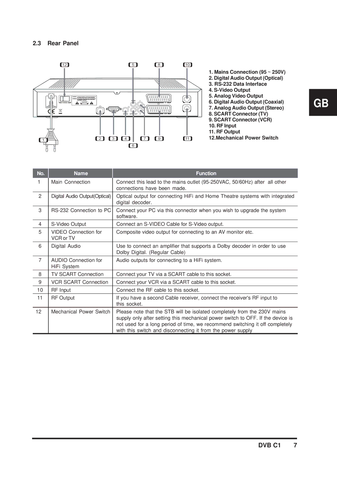
2.3Rear Panel
12 | 5 | 8 | 10 |
RF IN
RF OUT |
1 | 2 | 3 | 4 | 7 | 9 | 11 |
|
|
|
|
|
| |
|
|
|
| 6 |
|
|
1.Mains Connection (95 ~ 250V)
2.Digital Audio Output (Optical)
3.
4.
5.Analog Video Output
6.Digital Audio Output (Coaxial)
7.Analog Audio Output (Stereo)
8.SCART Connector (TV)
9.SCART Connector (VCR)
10.RF Input
11.RF Output
12.Mechanical Power Switch
GB
No. | Name | Function |
1 | Main Connection | Connect this lead to the mains outlet |
|
| connections have been made. |
2 | Digital Audio Output(Optical) | Optical output for connecting HiFi and Home Theatre systems with integrated |
|
| digital decoder. |
3 | Connect your PC via this connector when you wish to upgrade the system | |
|
| software. |
4 | Connect an | |
5 | VIDEO Connection for | Composite video output for connecting to an AV monitor etc. |
| VCR or TV |
|
6 | Digital Audio | Use to connect an amplifier that supports a Dolby decoder in order to use |
|
| Dolby Digital. (Regular Cable) |
7 | AUDIO Connection for | Audio outputs for connecting to a HiFi system. |
| HiFi System |
|
8 | TV SCART Connection | Connect your TV via a SCART cable to this socket. |
9 | VCR SCART Connection | Connect your VCR via a SCART cable to this socket. |
10 | RF Input | Connect the RF cable to this socket. |
11 | RF Output | If you have a second Cable receiver, connect the receiver's RF input to |
|
| this socket. |
12 | Mechanical Power Switch | Please note that the STB will be isolated completely from the 230V mains |
|
| supply only after setting this mechanical power switch to OFF. If the device is |
|
| not used for a long period of time, we recommend switching it off completely |
|
| with this switch and disconnecting it from the power supply |
