Overview
Component Features
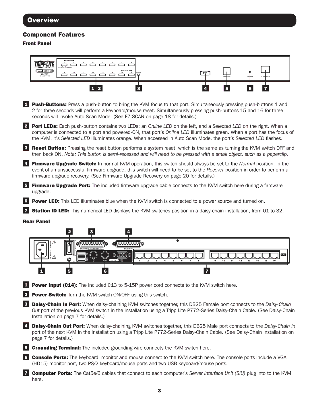
Front Panel
|
|
|
|
|
|
|
|
|
|
|
|
|
|
|
|
|
|
|
|
|
|
|
|
|
|
|
|
|
|
|
|
|
|
|
|
|
|
|
|
|
|
|
|
|
|
|
|
|
|
|
|
|
|
|
|
|
|
|
|
|
|
|
|
|
|
|
|
|
|
|
|
|
|
|
|
|
|
|
|
| 1 | 2 |
| 3 |
|
| 4 |
|
| 5 |
| 6 |
| 7 | |||||
1
2 for three seconds will perform a keyboard/mouse reset. Simultaneously pressing
2Port LEDs: Each
3Reset Button: Pressing the reset button performs a system reset, which is the same as turning the KVM switch OFF and
then back ON. Note: This button is
4Firmware Upgrade Switch: In normal KVM operation, this switch should always be set to the Normal position. In the event of an unsuccessful firmware upgrade, this switch will need to be set to the Recover position in order to perform a firmware upgrade recovery. (See Firmware Upgrade Recovery on page 20 for details.)
5Firmware Upgrade Port: The included firmware upgrade cable connects to the KVM switch here during a firmware upgrade.
6Power LED: This LED illuminates blue when the KVM switch is connected to a power source and turned on.
7Station ID LED: This numerical LED displays the KVM switches position in a
Rear Panel
2 |
|
|
| 3 |
|
| 4 | |||
|
|
|
|
|
|
|
|
|
|
|
|
|
|
|
|
|
|
|
|
|
|
|
|
|
|
|
|
|
|
|
|
|
|
|
|
|
|
|
|
|
|
|
|
1 | 5 | 6 | 7 |
1Power Input (C14): The included C13 to
2Power Switch: Turn the KVM switch ON/OFF using this switch.
3
4
5Grounding Terminal: The included grounding wire connects the KVM switch here.
6Console Ports: The keyboard, monitor and mouse connect to the KVM switch here. The console ports include a VGA (HD15) monitor port, two PS/2 keyboard/mouse ports and two USB keyboard/mouse ports.
7Computer Ports: The Cat5e/6 cables that connect to each computer’s Server Interface Unit (SIU) plug into to the KVM here.
3