Installing the USB-to-Serial Adapter (continued)
Uninstalling under Windows 2000 or Windows XP
Follow these steps in the event that you need to uninstall or reinstall the
1.From the Control Panel, select System.
2.Press the Hardware tab.
3.Click on Device Manager.
4.Scroll down to
5.Highlight your
6.Select the Action menu option.
7.Select Uninstall from the drop down menu.
8.Click OK at the Confirmation screen. Note that this also removes all the serial ports associated with your
Making external connections
RS-232 Serial Connections
Note: A DTE device is the communication source. A DCE device provides a communication channel between two
Figure 11 - DB9 connector pinout.
|
|
Data Carrier Detect (DCD) | 1 |
|
|
Receive Data (RxD) | 2 |
|
|
Transmit Data (TxD) | 3 |
|
|
Data Terminal Ready (DTR) | 4 |
|
|
Signal Ground (GND) | 5 |
|
|
Data Set Ready (DSR) | 6 |
|
|
Request To Send (RTS) | 7 |
|
|
Clear To Send (CTS) | 8 |
|
|
Ring Indicator (RI) | 9 |
|
|
DTE- and
Note: In many applications, DCEs are unnecessary. This allows you to use a null modem cable (modem eliminator cable) to directly connect two DTE type devices.
Figure 12 - Use of DTEs and DCEs in a
communication link.
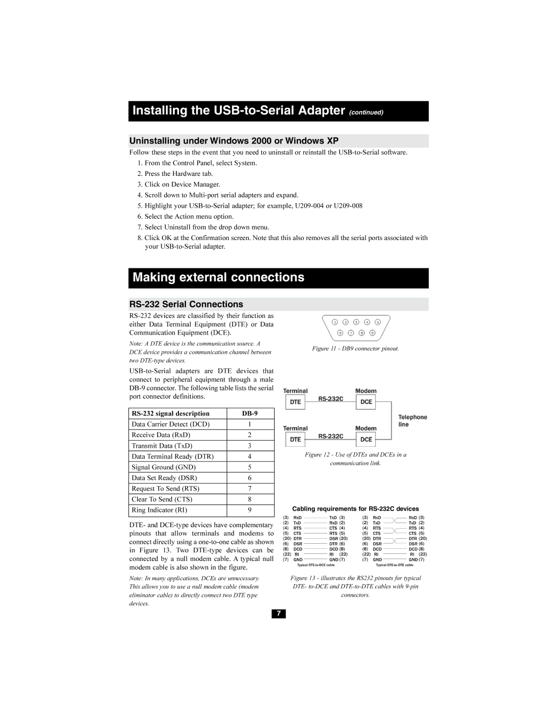
Cabling requirements for
Figure 13 - illustrates the RS232 pinouts for typical DTE- to-DCE and DTE-to-DTE cables with 9-pin connectors.
7