user manual
TA-890
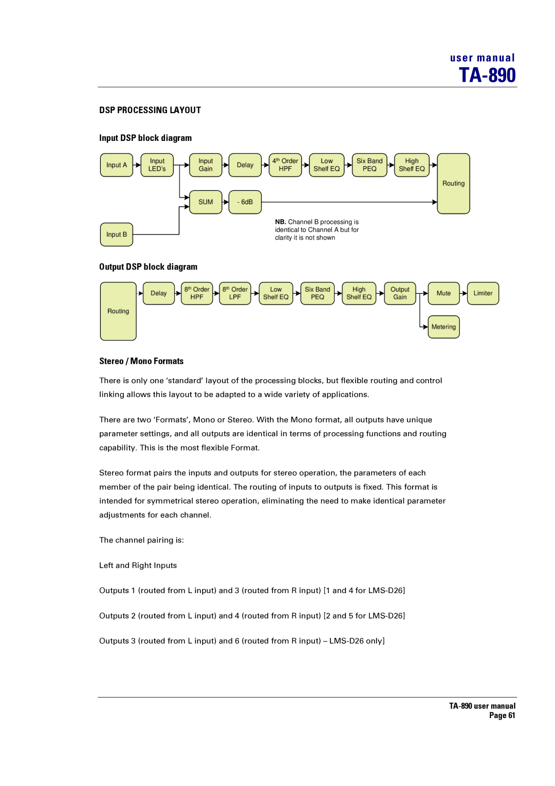
DSP PROCESSING LAYOUT
Input DSP block diagram
Input A
Input
Input
Delay
4th Order | Low | Six Band | High |
LED’s
Input B
Gain
SUM - 6dB
HPF | Shelf EQ | PEQ | Shelf EQ |
Routing
NB. Channel B processing is identical to Channel A but for clarity it is not shown
Output DSP block diagram
Delay |
| 8th Order |
| 8th Order |
| Low |
| Six Band |
| High |
| Output |
| HPF |
| LPF |
| Shelf EQ |
| PEQ |
| Shelf EQ |
| Gain | |
|
|
|
|
|
|
|
Routing
Mute Limiter
![]() Metering
Metering
Stereo / Mono Formats
There is only one ‘standard’ layout of the processing blocks, but flexible routing and control linking allows this layout to be adapted to a wide variety of applications.
There are two ‘Formats’, Mono or Stereo. With the Mono format, all outputs have unique parameter settings, and all outputs are identical in terms of processing functions and routing capability. This is the most flexible Format.
Stereo format pairs the inputs and outputs for stereo operation, the parameters of each member of the pair being identical. The routing of inputs to outputs is fixed. This format is intended for symmetrical stereo operation, eliminating the need to make identical parameter adjustments for each channel.
The channel pairing is:
Left and Right Inputs
Outputs 1 (routed from L input) and 3 (routed from R input) [1 and 4 for
Outputs 2 (routed from L input) and 4 (routed from R input) [2 and 5 for
Outputs 3 (routed from L input) and 6 (routed from R input) –