Manuals
/
Ultimate Products
/
Household Appliance
/
Garage Door Opener
Ultimate Products
UP-206
manual
Model DC
Models:
UP-206
1
31
46
46
Download
46 pages
612 b
28
29
30
31
32
33
34
35
Troubleshooting
Install
Warranty
Dimension
Fixing Control Problems
Completed Operator set up view
Ultimate Air-Powered Operator
Cable jumping solutions
Page 31
Image 31
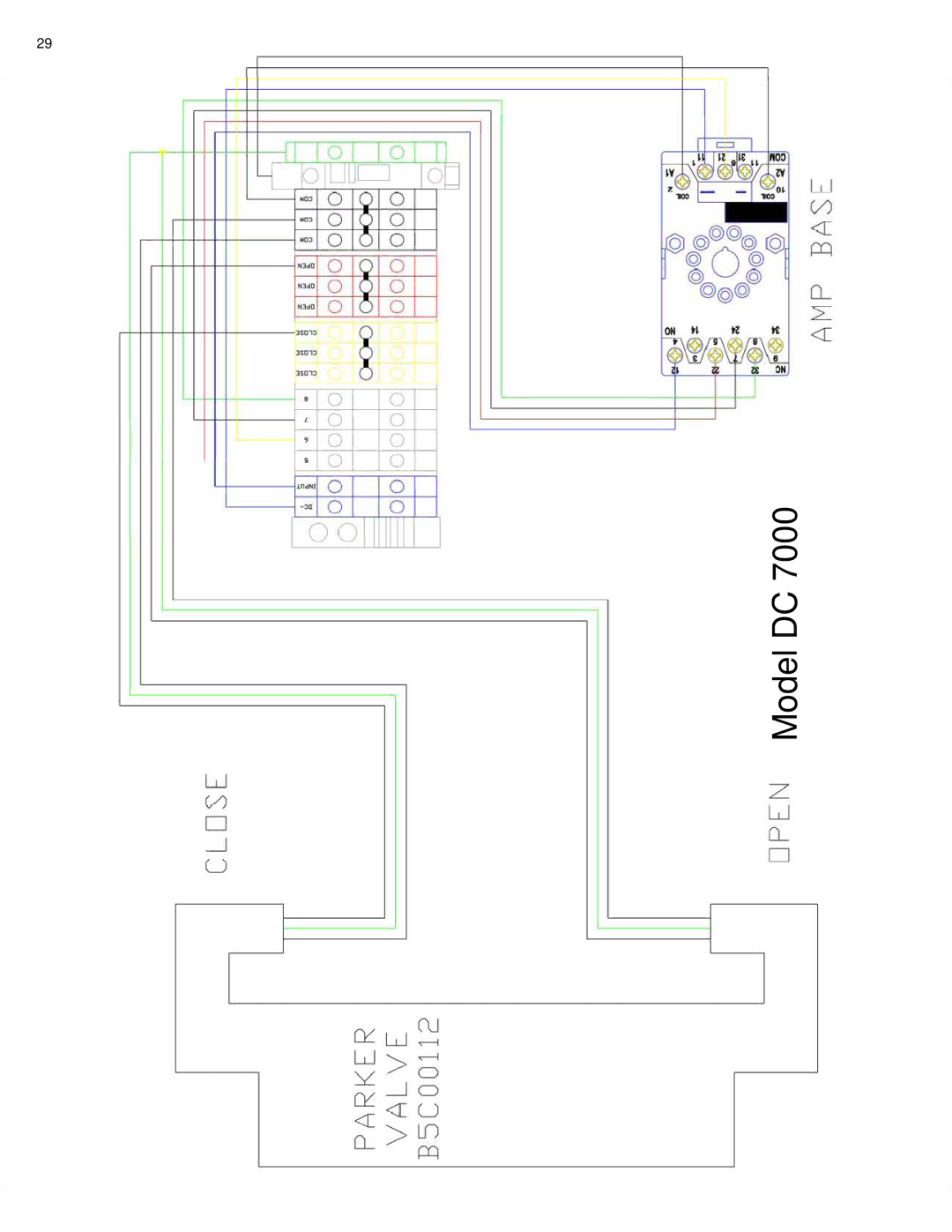
29
Model DC 7000
Page 30
Page 32
Page 31
Image 31
Page 30
Page 32
Contents
Supplies needed but not included with this kit
Necessary tools
Part 1BELT Installation
Installing Tensioner Kit Before installing the air cylinder,
Installing Tensioner Kit
As shown on
From belt before installing belt onto Operator
Hanging Operator
Page
Page
Setting Open and Close Door Limits
Completed Operator set up view
Installation Chain Drive
Part 2INSTALLING Chain Drive
Step Installing Chain
Speed Control Kit
Sprocket Assembly Part No. SPK1000
Step
Completed Chain Operator set up, see
Part
Installing Air Lines
Part 6a U Series
Part 6b S Series
Door adjustments and fine tuning
Troubleshooting
Install Signal Senders
Fixing Door or Operator Problems
Fixing Control Problems
Putting the cable back on the drum
Automatic Oiler Adjustment Cable Jumping
Cable jumping solutions
Door cable is jumping
2624
Model DC
Model DC
Model DC
Home of the Best Buy Guarantee
Photo Amplifier Wiring Directions
Limit Switch Wiring and Mounting
Suggested Installation of Magnetic Loop
Wiring Diagram Finder Timer to Control Box
Operator with Belt Operator with Chain
Ring AP1004 Check ball
Model
Power Supply
Dimensions
Control Box
Operators
Operators with belts
Superior or Economy Air-Powered Operators
Ultimate Air-Powered Operator
Operators with chains
Operators with Automatic Oilers
Cylinder Oiling
Operators without Oiler
Tools and materials needed
Items included in the kit
Cup Seals
Breather Vents and Check Ball
Piston Rod Seals
Needle Valve
Page
Technical assistance and salespeople are available Monday
Top
Page
Image
Contents