34
Wiring Diagram: Finder Timer to Control Box
!!DISCONNECT POWER BEFORE PROCEEDING!!
1.Timer is supplied
2.Unplug Photo Amplifier from Amplifier Base.
3.Unclip Amplifier Base from existing Din Rail.
4.Remove existing Din Rail by removing the two screws that attach it to the back panel.
5.Install new Din Rail with Timer attached to the back panel. (Screws are
6.Reattach Amplifier Base to Din Rail.
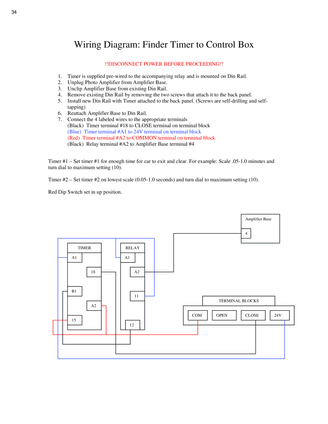
7.Connect the 4 labeled wires to the appropriate terminals
(Black) Timer terminal #18 to CLOSE terminal on terminal block (Blue) Timer terminal #A1 to 24V terminal on terminal block (Red) Timer terminal #A2 to COMMON terminal on terminal block (Black) Relay terminal #A2 to Amplifier Base terminal #4
Timer #1 – Set timer #1 for enough time for car to exit and clear. For example:
Timer #2 – Set timer #2 on lowest scale
Red Dip Switch set in up position.
TIMER
A1
18
B1
A2
15
RELAY
A1
A2
11
12
Amplifier Base
4
TERMINAL BLOCKS
|
|
|
|
|
|
|
|
|
|
|
|
| COM |
| OPEN |
| CLOSE |
| 24V |
| |||
|
|
|
|
|
|
|
|
|
|
|
|
|
|
|
|
|
|
|
|
|
|
|
|
|
|
|
|
|
|
|
|
|
|
|
|
|
|
|
|
|
|
|
|
|
|
|
|
|
|
|
|
|
|
|
|
|
|
|
|