Accessory
Installation
Continued
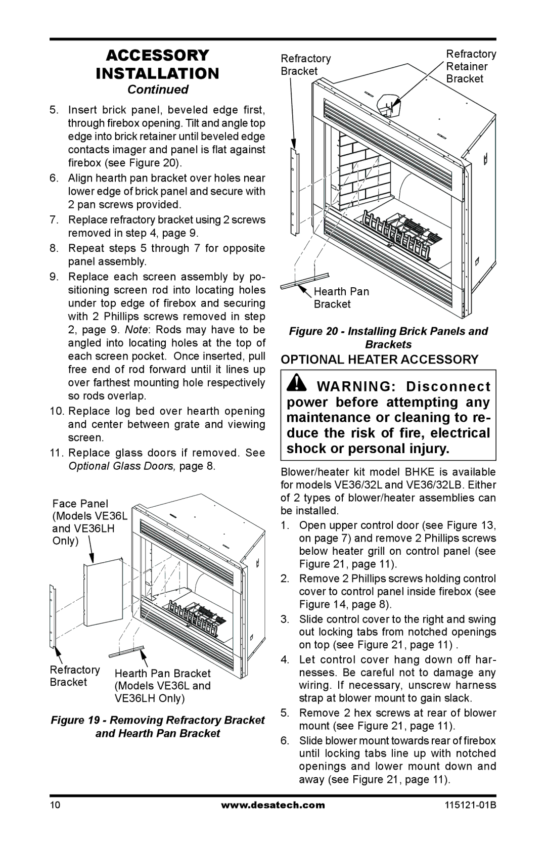
5.Insert brick panel, beveled edge first, through firebox opening. Tilt and angle top edge into brick retainer until beveled edge contacts imager and panel is flat against firebox (see Figure 20).
6.Align hearth pan bracket over holes near lower edge of brick panel and secure with 2 pan screws provided.
7.Replace refractory bracket using 2 screws removed in step 4, page 9.
8.Repeat steps 5 through 7 for opposite panel assembly.
9.Replace each screen assembly by po- sitioning screen rod into locating holes under top edge of firebox and securing with 2 Phillips screws removed in step 2, page 9. Note: Rods may have to be angled into locating holes at the top of each screen pocket. Once inserted, pull free end of rod forward until it lines up over farthest mounting hole respectively so rods overlap.
10.Replace log bed over hearth opening and center between grate and viewing screen.
11.Replace glass doors if removed. See Optional Glass Doors, page 8.
Face Panel
(Models VE36L
and VE36LH
Only)
Refractory | Hearth Pan Bracket | |
Bracket | ||
(Models VE36L and | ||
| ||
| VE36LH Only) |
Figure 19 - Removing Refractory Bracket
and Hearth Pan Bracket
Refractory | Refractory | |
Retainer | ||
Bracket | ||
Bracket | ||
|
![]() Hearth Pan
Hearth Pan
Bracket
Figure 20 - Installing Brick Panels and
Brackets
OPTIONAL HEATER ACCESSORY
![]() WARNING: Disconnect power before attempting any maintenance or cleaning to re- duce the risk of fire, electrical shock or personal injury.
WARNING: Disconnect power before attempting any maintenance or cleaning to re- duce the risk of fire, electrical shock or personal injury.
Blower/heater kit model BHKE is available for models VE36/32L and VE36/32LB. Either of 2 types of blower/heater assemblies can be installed.
1.Open upper control door (see Figure 13, on page 7) and remove 2 Phillips screws below heater grill on control panel (see Figure 21, page 11).
2.Remove 2 Phillips screws holding control cover to control panel inside firebox (see
Figure 14, page 8).
3.Slide control cover to the right and swing out locking tabs from notched openings on top (see Figure 21, page 11) .
4.Let control cover hang down off har- nesses. Be careful not to damage any wiring. If necessary, unscrew harness strap at blower mount to gain slack.
5.Remove 2 hex screws at rear of blower mount (see Figure 21, page 11).
6.Slide blower mount towards rear of firebox until locking tabs line up with notched openings and lower mount down and away (see Figure 21, page 11).
10 | www.desatech.com |