INSTALLATION
Continued
5.Snap assembled trim kit onto shoulder screws around face to lock fireplace into mantel facing.
6.Attach mantel to base according to mantle instructions.
BUILT-IN INSTALLATION
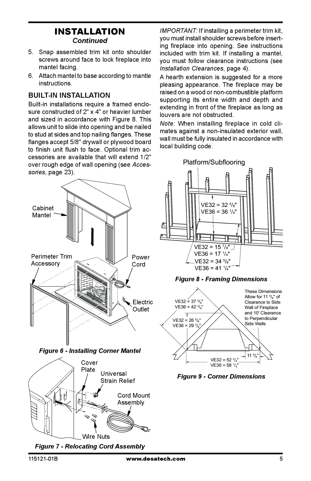
Cabinet
Mantel 
Perimeter Trim | Power |
Accessory | Cord |
 Electric
Outlet
Figure 6 - Installing Corner Mantel
IMPORTANT: If installing a perimeter trim kit, you must install shoulder screws before insert- ing fireplace into opening. See instructions included with trim kit. If installing a mantel, you must follow clearance instructions (see Installation Clearances, page 4).
A hearth extension is suggested for a more pleasing appearance. The fireplace may be raised on a wood or
Note: When installing fireplace in cold cli- mates against a
Platform/Subflooring
VE32 = 32 5/8"
VE36 = 36 1/4"
VE32 = 15 7/8"
VE36 = 17 1/4"
VE32 = 34 5/8"
VE36 = 41 1/4"
Figure 8 - Framing Dimensions
|
|
|
| These Dimensions |
VE32 = 37 5/8" | Allow for 11 5/8" of | |||
Clearance to Side | ||||
VE36 = 42 3/8" | Wall of Fireplace | |||
|
|
|
| and 10' Clearance |
|
|
|
| |
VE32 = 26 5/8" | to Perpendicular | |||
VE36 = 29 3/8" | Side Walls | |||
|
|
|
| 11 5/8" |
|
|
|
| |
|
|
|
| |
|
|
|
| 3 |
Cover Plate
Universal
Strain Relief
Cord Mount
Assembly
VE32 = 52 /4" |
VE36 = 58 1/4" |