Manuals
/
Vanguard Heating
/
Kitchen Appliance
/
Oven
Vanguard Heating
SBVBN(C), SBVBP(C)
installation manual
Installing Remote Receiver, Continued
Models:
SBVBP(C)
SBVBN(C)
1
16
32
32
Download
32 pages
50.01 Kb
13
14
15
16
17
18
19
20
Troubleshooting
Specs
Install
Parts list
Wiring Diagram
Warranty
Stove Body Assembly
Manual Lighting Procedure
Cleaning And Maintenance
Installation Precautions
Page 16
Image 16
Page 15
Page 17
Page 16
Image 16
Page 15
Page 17
Contents
OWNER’S OPERATION AND INSTALLATION MANUAL
FOR YOUR SAFETY
FOR YOUR SAFETY WHAT TO DO IF YOU SMELL GAS
Do not try to light any appliance Do not touch any electrical switch
SAFETY INFORMATION
SBVBNC AND SBVBPC CAST IRON STOVE AND BURNER SYSTEM
WARNINGS
DANGER Carbon monoxide poisoning may lead to death
PRODUCT FEATURES
OWNER’S MANUAL
PRODUCT IDENTIFICATION
LOCAL CODES
LOCATION AND SPACE REQUIREMENTS
PRE-INSTALLATION PREPARATION
etc. in the air exist, may discolor walls
CAST IRON STOVE AND B-VENT BURNER SYSTEM ASSEMBLY
STOVE BODY ASSEMBLY
Continued
INSTALLING B-VENT BURNER SYSTEM INTO STOVE BODY
INSTALLING OPTIONAL BLOWER ACCESSORY
CAST IRON STOVE AND DIRECT-VENT BURNER SYSTEM ASSEMBLY
INSTALLING REAR COVER
INSTALLATION
INSTALLATION PRECAUTIONS
TYPE B-VENT INSTALLATION Listed B-0 or Greater
VENTING
VENTING INSTALLATION
INSTALLATION OF LISTED B-1 VENT
INSTALLING VENT SYSTEM IN A CHASE
CHECKING VENT CAPACITY
CHIMNEYS
HIGH ALTITUDE INSTALLATION
RELINING SYSTEMS
TROUBLESHOOTING VENTING PROBLEMS
CAST IRON STOVE AND B-VENT BURNER SYSTEM INSTALLATION
INSTALLING GAS PIPING TO STOVE LOCATION
FLUE GAS SPILLAGE
Installation Items Needed
CAUTION Use only new, black iron or steel pipe. Inter
CONNECTING STOVE/ BURNER SYSTEM TO GAS SUPPLY
Pressure Testing Gas Supply Piping System
Pressure Testing Burner System Gas Connections
CHECKING GAS CONNECTIONS
INSTALLING OPTIONAL WALL MOUNT SWITCH GWMS2
INSTALLING OPTIONAL WALL MOUNTED THERMOSTAT - GWMT1
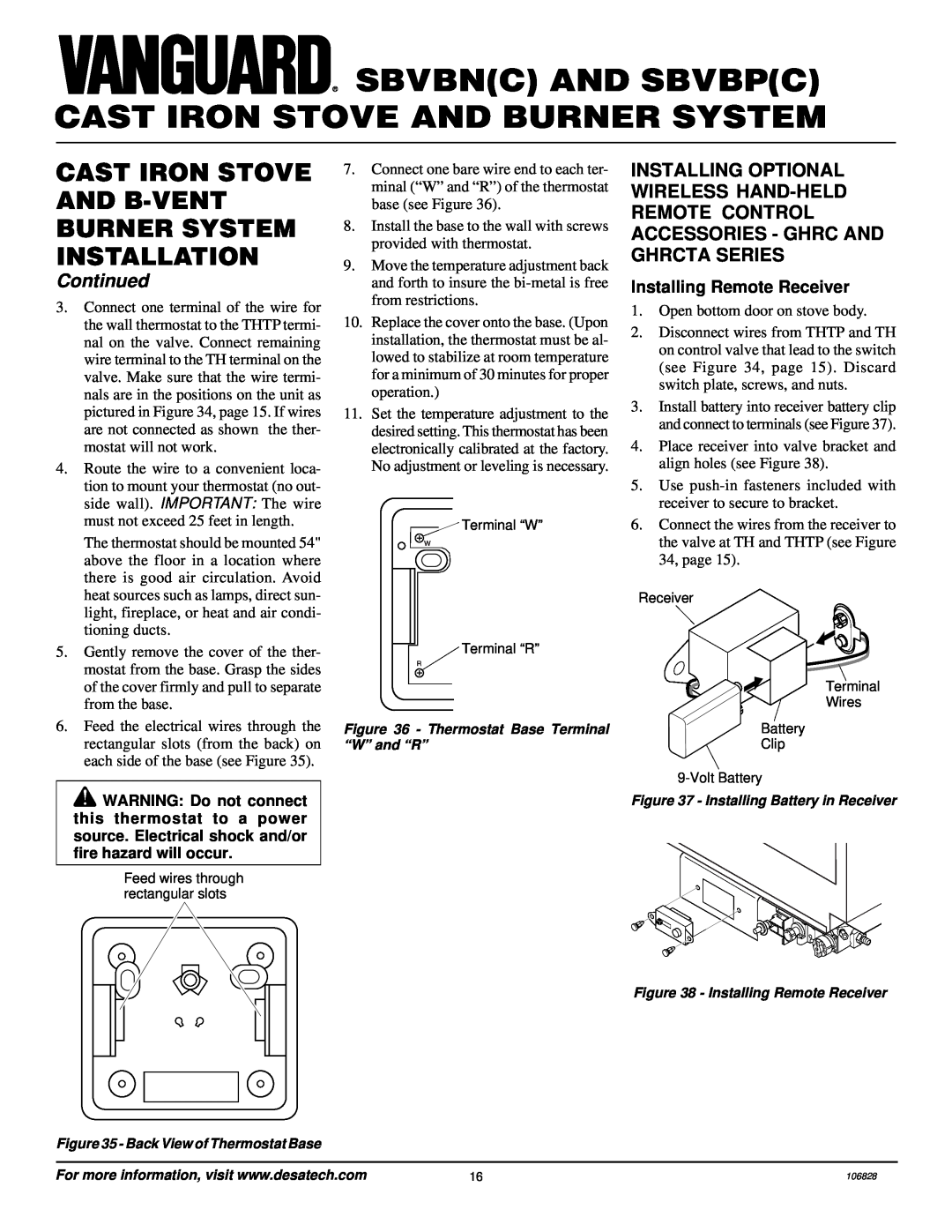
Installing Remote Receiver
Installing 9-Volt Battery in Hand- Held Remote Control Unit
REMOVING/REPLACING GLASS DOOR
INSTALLING LOGS, LAVA ROCK, AND GLOWING EMBERS
Figure 44 - Installing Log No
Figure 45 - Installing Log No
Figure 43 - Installing Log No Figure 46 - Installing Log No
FOR YOUR SAFETY READ BEFORE LIGHTING
MANUAL LIGHTING PROCEDURE
OPERATING STOVE WITH B-VENT BURNER SYSTEM
LIGHTING INSTRUCTIONS
OPTIONAL REMOTE
Thermostat Control Operation
GHRC Series Operation
GHRCTA Series Operation
OPERATING OPTIONAL BLOWER ACCESSORY
PILOT ASSEMBLY
INSPECTING BURNERS
OPERATING OPTIONAL GWMT1 WALL MOUNTED THERMOSTAT
CLEANING AND MAINTENANCE
WARNING Turn off burner system and let cool before cleaning
GLASS DOOR
PILOT AND BURNERS
TROUBLESHOOTING
OBSERVED PROBLEM
POSSIBLE CAUSE
REMEDY
REMEDY
Clean pilot see Cleaning and Mainte
WARNING If you smell gas Shut off gas supply
Do not try to light any appliance
If you cannot reach your gas supplier, call the fire department
REPLACEMENT PARTS
TECHNICAL SERVICE
WIRING DIAGRAM
SERVICE HINTS
SPECIFICATIONS
ACCESSORIES
RECEIVER AND HAND-HELD REMOTE CONTROL KIT GHRC
WALL MOUNTED ON/OFF SWITCH - GWMS2 Not Shown
ILLUSTRATED PARTS BREAKDOWN
SBVBNC SBVBPC
23-3
23-4
PARTS LIST
PART NUMBER
DESCRIPTION
PARTS AVAILABLE - NOT SHOWN
AMITY SCIVFC* SERIES PSCIVFC* SERIES
Indicates Color Suffix Designation
PART
WARRANTY INFORMATION
LIMITED WARRANTY B-VENT BURNER SYSTEM AND AMITY STOVE CHASSIS
KEEP THIS WARRANTY
INTERNATIONAL
Top
Page
Image
Contents