usaGe | |
|
|
Laser Firing Sequence
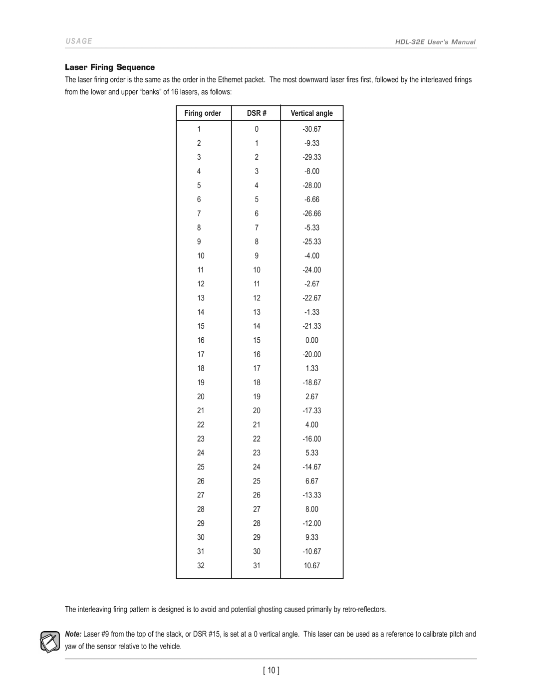
The laser firing order is the same as the order in the Ethernet packet. The most downward laser fires first, followed by the interleaved firings from the lower and upper “banks” of 16 lasers, as follows:
Firing order | DSR # | Vertical angle |
|
|
|
1 | 0 | |
2 | 1 | |
3 | 2 | |
4 | 3 | |
5 | 4 | |
6 | 5 | |
7 | 6 | |
8 | 7 | |
9 | 8 | |
10 | 9 | |
11 | 10 | |
12 | 11 | |
13 | 12 | |
14 | 13 | |
15 | 14 | |
16 | 15 | 0.00 |
17 | 16 | |
18 | 17 | 1.33 |
19 | 18 | |
20 | 19 | 2.67 |
21 | 20 | |
22 | 21 | 4.00 |
23 | 22 | |
24 | 23 | 5.33 |
25 | 24 | |
26 | 25 | 6.67 |
27 | 26 | |
28 | 27 | 8.00 |
29 | 28 | |
30 | 29 | 9.33 |
31 | 30 | |
32 | 31 | 10.67 |
|
|
|
The interleaving firing pattern is designed is to avoid and potential ghosting caused primarily by
note: Laser #9 from the top of the stack, or DSR #15, is set at a 0 vertical angle. This laser can be used as a reference to calibrate pitch and yaw of the sensor relative to the vehicle.
[ 10 ]
