13" (330 mm)
Max.
Top View |
|
Straight Venting | FP1598 |
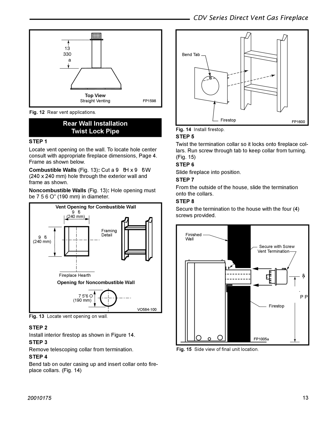
Fig. 12 Rear vent applications.
Rear Wall Installation
Twist Lock Pipe
STEP 1
Locate vent opening on the wall. To locate hole center consult with appropriate fireplace dimensions, Page 4. Frame as shown below.
Combustible Walls (Fig. 13): Cut a 9³⁄₈”H x 9³⁄₈” W (240 x 240 mm) hole through the exterior wall and frame as shown.
Noncombustible Walls (Fig. 13): Hole opening must be 7¹⁄₂” (190 mm) in diameter.
Vent Opening for Combustible Wall
9³⁄₈”
(240 mm)
Framing
9 ”Detail ³⁄₈
(240 mm)
Fireplace Hearth
Opening for Noncombustible Wall
7¹⁄₂”
(190 mm)
Fig. 13 Locate vent opening on wall.
STEP 2
Install interior firestop as shown in Figure 14.
STEP 3
Remove telescoping collar from termination.
STEP 4
Bend tab on outer casing up and insert collar onto fire- place collars. (Fig. 14)
CDV Series Direct Vent Gas Fireplace
Bend Tab
Firestop | FP1600 |
|
Fig. 14 Install firestop.
STEP 5
Twist the termination collar so it locks onto fireplace col- lars. Run screw through tab to keep collar from turning. (Fig. 15)
STEP 6
Slide fireplace into position.
STEP 7
From the outside of the house, slide the termination onto the collars.
STEP 8
Secure the termination to the house with the four (4) screws provided.
Finished
Wall
Secure with Screw
Vent Termination
C
L
22”
(559 mm)
Firestop
FP1005a
Fig. 15 Side view of final unit location.
20010175 | 13 |
