STEP 2
Slide venting component on collar of fireplace. Secure component to fireplace by running a screw
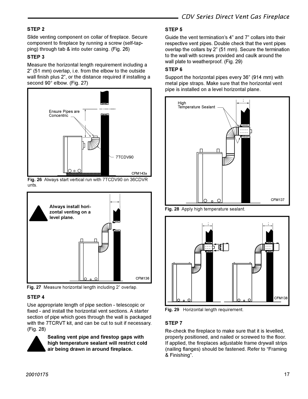
STEP 3
Measure the horizontal length requirement including a 2” (51 mm) overlap, i.e. from the elbow to the outside wall finish plus 2”, or the distance required if installing a second 90° elbow. (Fig. 27)
CDV Series Direct Vent Gas Fireplace
STEP 5
Guide the vent termination’s 4” and 7” collars into their respective vent pipes. Double check that the vent pipes overlap the collars by 2” (51 mm). Secure the termination to the wall with screws provided and caulk around the wall plate to weatherproof. (Fig. 29)
STEP 6
Support the horizontal pipes every 36” (914 mm) with metal pipe straps. Make sure that the horizontal vent pipe is installed on a level horizontal plane.
High
X
Ensure Pipes are
Concentric
�
![]()
![]() 7TCDV90
7TCDV90
CFM143a
Fig. 26 Always start vertical run with 7TCDV90 on 36CDVR unts.
X
Always install hori- zontal venting on a level plane.
CFM136
Fig. 27 Measure horizontal length including 2” overlap.
STEP 4
Use appropriate length of pipe section - telescopic or fixed - and install the horizontal vent sections. A starter section of pipe which goes through the wall is packaged with the 7TCRVT kit, and can be cut to suit if necessary. (Fig. 28)
Sealing vent pipe and firestop gaps with high temperature sealant will restrict cold air being drawn in around fireplace.
Temperature Sealant
CFM137
Fig. 28 Apply high temperature sealant.
X | X |
![]() CFM138
CFM138
Fig. 29 Horizontal length requirement.
STEP 7
20010175 | 17 |