CDV Series Direct Vent Gas Fireplace
Zero Clearance Sleeve | Screws | |
(if required) | ||
| ||
| 7TDVSNORK | |
Firestop | (Snorkel) | |
| ||
7” Pipe | 4” (102mm) | |
Clearance | ||
| ||
| Min. | |
24” (610mm) | Window | |
Well | ||
Minimum* |
| |
| Gravel | |
| Drain | |
| Foundation Wall | |
| *A minimum of 24” (610mm) ver- | |
| tical pipe must be installed when | |
| using the 7TDVSNORK Kit. | |
| *The 22” (559mm) vertical rise | |
| (center to center) of the snorkel | |
| may be included for calculationof | |
| max. horizontal run. | |
BG402 |
|
Fig. 48 Below grade installation.
Do not back fill around snorkel. A clearance of at least 4” (102 mm) must be maintained between snorkel and the soil.
If the foundation is recessed, use recess brackets (not supplied) for securing lower portion of the snorkel. Fasten brackets to wall first, then secure to snorkel with self drilling #8 x 1/2 sheet metal screws. It will be necessary to extend vent pipes out as far as protruding wall face. (Fig. 49)
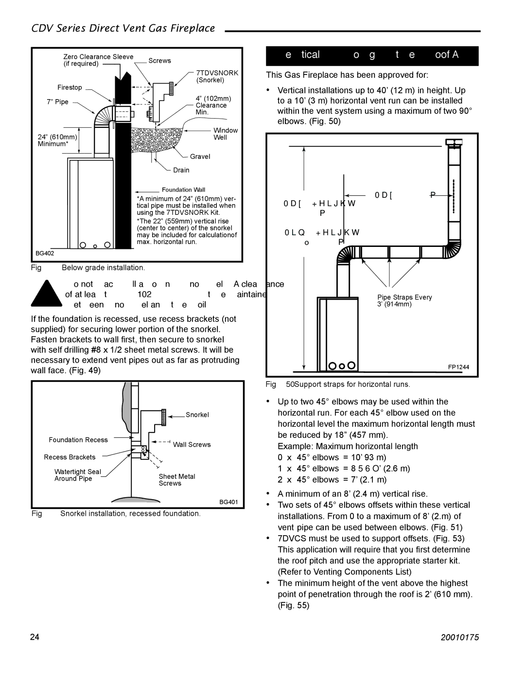
Vertical Through-the-Roof Applications
This Gas Fireplace has been approved for:
•Vertical installations up to 40’ (12 m) in height. Up to a 10’ (3 m) horizontal vent run can be installed within the vent system using a maximum of two 90° elbows. (Fig. 50)
Max. 10' (3m)
Max. Height
40' (12m)
Min. Height 7���' (2.3m)
Pipe Straps Every 3’ (914mm)
FP1244
Fig. 50 Support straps for horizontal runs.
Foundation Recess
Recess Brackets
Watertight Seal
Around Pipe
![]()
![]() Snorkel
Snorkel
![]()
![]() Wall Screws
Wall Screws
Sheet Metal
Screws
BG401
• Up to two 45° elbows may be used within the | ||
horizontal run. For each 45° elbow used on the | ||
horizontal level the maximum horizontal length must | ||
be reduced by 18” (457 mm). | ||
Example: Maximum horizontal length | ||
0 | x | 45° elbows = 10’ 93 m) |
1 | x | 45° elbows = 8¹⁄₂’ (2.6 m) |
2 | x | 45° elbows = 7’ (2.1 m) |
• A minimum of an 8’ (2.4 m) vertical rise. | ||
• Two sets of 45° elbows offsets within these vertical | ||
Fig. 49 Snorkel installation, recessed foundation.
installations. From 0 to a maximum of 8’ (2.m) of |
vent pipe can be used between elbows. (Fig. 51) |
• 7DVCS must be used to support offsets. (Fig. 53) |
This application will require that you first determine |
the roof pitch and use the appropriate starter kit. |
(Refer to Venting Components List) |
• The minimum height of the vent above the highest |
point of penetration through the roof is 2’ (610 mm). |
(Fig. 55) |
24 | 20010175 |