CDV Series Direct Vent Gas Fireplace
Gas Inlet and Manifold Pressures
|
| Natural | LP (Propane) |
Inlet Minimum | 5.5” w.c. | 11.0” w.c. | |
Inlet Maximum | 14.0” w.c. | 14.0” w.c. | |
Manifold Pressure | 3.5” w.c. | 10.0” w.c. | |
|
|
|
|
High Elevations
Input ratings are shown in BTU per hour and are certified without deration for elevations up to 4,500 feet (1,370 m) above sea level.
For elevations above 4,500 feet (1,370 m) in USA, installations must be in accordance with the cur- rent ANSI Z223.1/NFPA 54 and/or local codes hav- ing jurisdiction.
In Canada, please consult provincial and/or local authorities having jurisdiction for installations at elevations above 4,500 feet (1,370 m).
Gas Line Installation
When purging the gas lines, the front win- dow frame assembly must be removed.
The gas pipeline can be brought in through the rear of the appliance as well as the bottom. Knockouts are provided on the bottom behind the valve to allow for the gas pipe installation and testing of any gas connection. It is most convenient to bring the gas line in from the rear right side of the valve as this allows fan installation or removal without disconnecting the gas line.
The gas line connection can be made with properly
The gas control is equipped with a captured screw type pressure test point, therefore it is not necessary to pro- vide a 1/8” test point up stream of the control.
When using copper or flex connector use only approved fittings. Always provide a union when using black iron pipe so the gas line can be easily disconnected for burner or fan servicing. See gas specification for pres- sure details and ratings.
The fireplace valve must not be subjected to any test pressures exceeding 1/2 psi. Isolate or disconnect this and any other gas appliance control from the gas line when pressure testing.
Remote ON/OFF Switch
Installation
1.Carefully unwrap the remote wire that is attached to the valve. There are two 1/2” (13 mm) knockouts, one on each side of the outer casing.
2.Remove the knockout desired and insert the plastic snap bushing on the remote wire in the 1/2” hole. Feed the remote wire through the outer casing.
3.Attach the wire to an ON/OFF switch and install the switch into the receptacle box. (Fig. 6)
Remote ON/OFF Switch or Thermostat
or Remote Control
TP
TH
Gas
TP Control
Valve
tinned 3/8” copper tubing, 3/8” rigid pipe or an ap- proved flex connector. Since some municipalities have additional local codes, it is always best to consult your local authority and the National Fuel Gas Code, ANSI
![]() TH
TH
Fig. 6 Remote switch wiring diagram.
FP1224
Z223.1/NFPA 54 in the USA or the
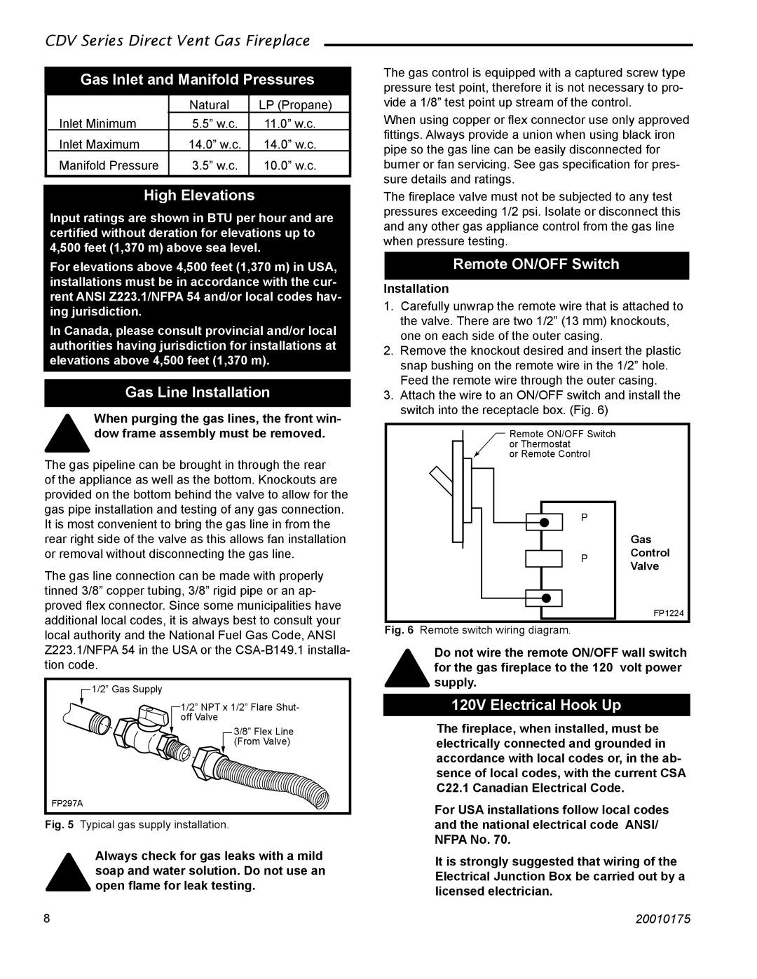
1/2” Gas Supply
1/2” NPT x 1/2” Flare Shut- off Valve
3/8” Flex Line
(From Valve)
FP297A
Fig. 5 Typical gas supply installation.
Always check for gas leaks with a mild soap and water solution. Do not use an open flame for leak testing.
Do not wire the remote ON/OFF wall switch for the gas fireplace to the 120 volt power supply.
120V Electrical Hook Up
The fireplace, when installed, must be electrically connected and grounded in accordance with local codes or, in the ab- sence of local codes, with the current CSA C22.1 Canadian Electrical Code.
For USA installations follow local codes and the national electrical code ANSI/ NFPA No. 70.
It is strongly suggested that wiring of the Electrical Junction Box be carried out by a licensed electrician.
8 | 20010175 |