HORIZONTALINSTALIATION
Step 1. Set lhe appliance in it'sdesired location. Check to determine if wall studs or roof rafters are in the way when the venting system is attached.lf this is the case,you may want to adjust the location of the appliance.
Step 2. Vent pipe and fittings are designed with special
NOTE:
1)
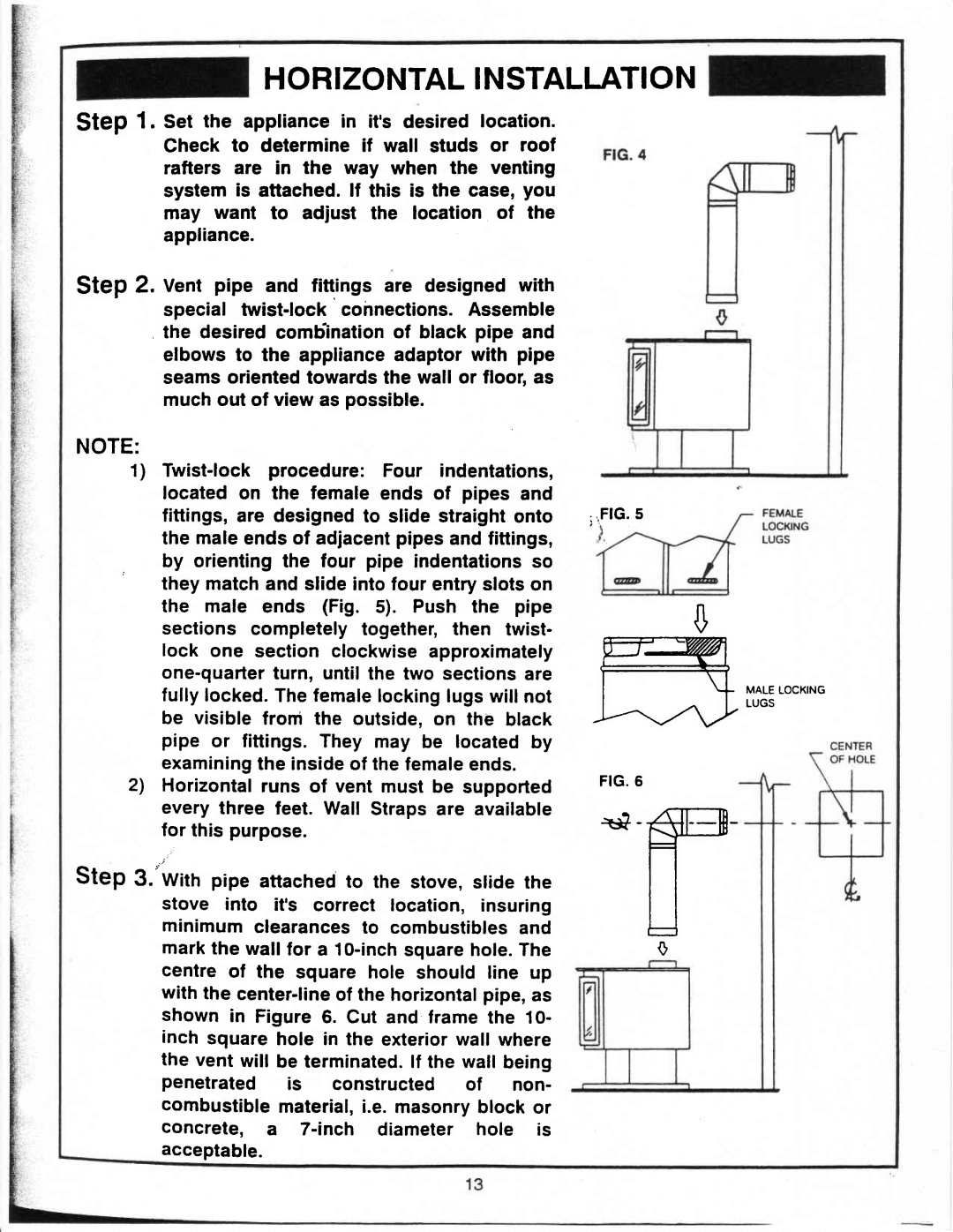
. by orientingthe four pipe indentationsso they matchand slide intofour entryslotson the male ends (Fig. 5). Push the pipe sections completelytogether,then twist- lock one section clockwiseapproximately
;iFlG'5
ru
ITI
$
fullylocked.Thefemalelockinglugswill not be visible from the outside,on the black pipe or fittings.They may be locatedby examiningthe insideof thefemaleends.
2')Horizontalruns of vent must be supported every three feet. Wall Strapsare available for this purpose.
Step 3.'Withpipe attachedto the stove,slide the stove into it'scorrect location, insuring minimumclearancesto combustiblesand markthe wallfor a
the vent will be terminatedlf. the wallbeing penetrated is constructed of non-
combustiblematerial,.e.masonryblock or concrete, a
F I G . 6
\*-ffi
F
I
tJ
0
MALELOCKING LUGS
acceptable.