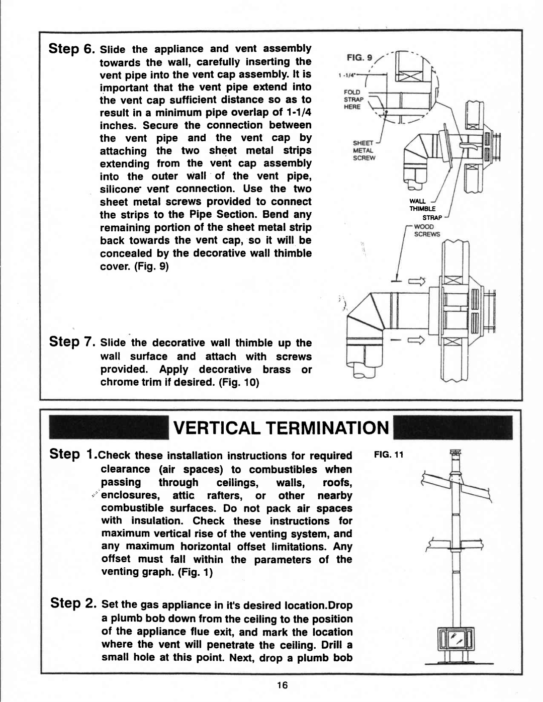
Step 6. SliOe the appliance and vent assembly towards the wall, carefully insertingthe vent pipe into the vent cap assembly.lt is important that the vent pipe extend into the vent cap sufficient distance so as to resuftin a minimumpipe overlapof
Step 7. Sliae the decorativewall thimble up the wall surface and attach with screws provided. Apply decorative brass or chrometrim if desired.(Fig.10)
WALL THIMELE
STRAP
VERTICALTERMINATION
Step l.Check these instatlationinstructionsfor required FtG .11
clearance (air spaces) to combustibles when
passing through ceilings, walls, roofs, ,'enclosures, attic rafters, or other nearby
combustiblesurfaces. Do not pack air spaces with insulation. Check these instructions for maximumverticalrise of the ventingsystem,and any maximumhorizontaloffset limitations.Any offset must fall within the parameters of the ventinggraph.(Fig.t)
Step 2. Setthe gas appliancein it,sdesiredlocation.Drop
aplumbbob downfrom the ceilingto the position of the applianceflue exit, and mark the location where the vent will penetratethe ceiling.Drill a small hole at this point. Next,drop a plumb bob
1 6