S T E P 6 B L A C K B A G
AB5
AB3
AD2
AB4
AJ6
AD1
AJ1
AC1 | AC3 |
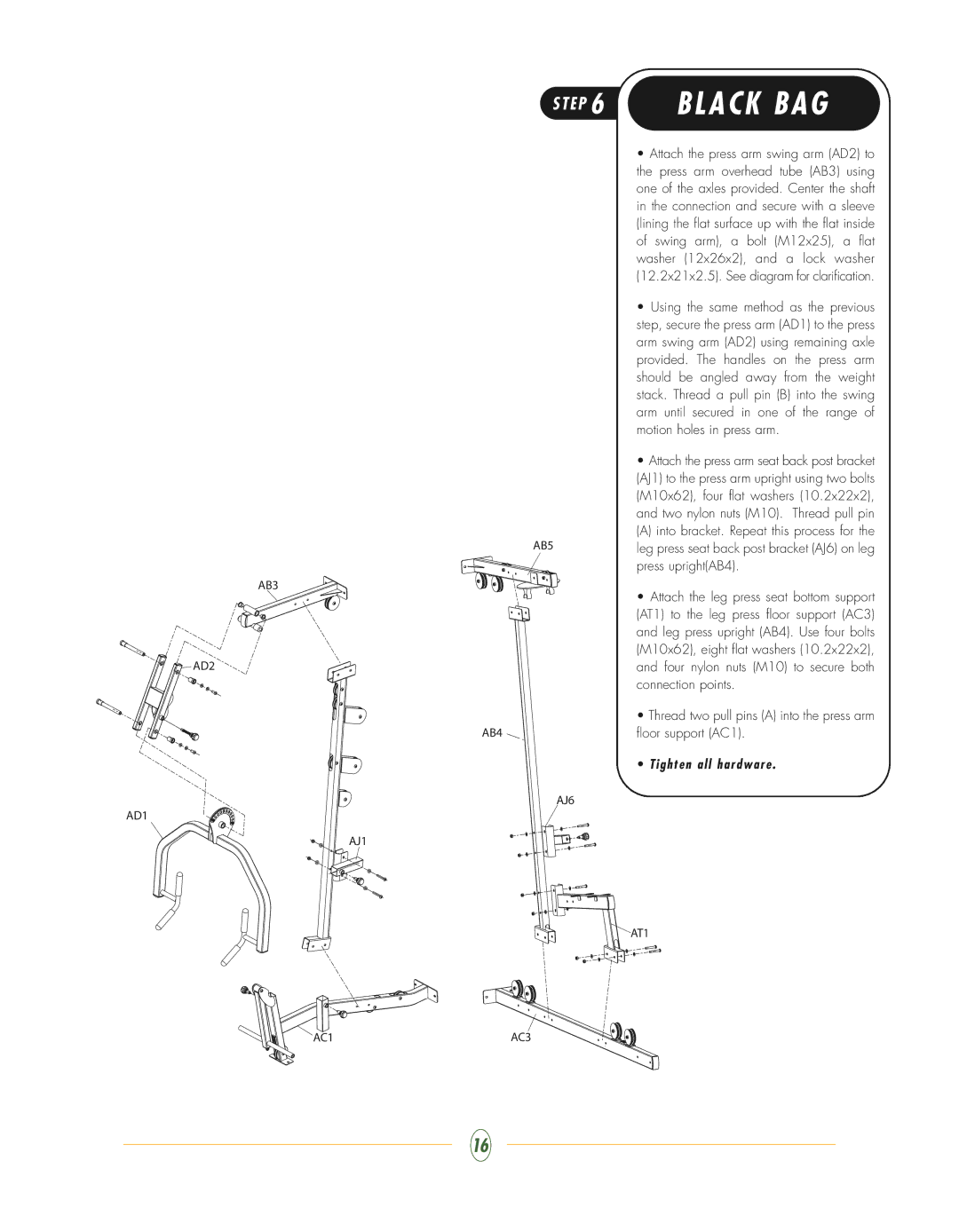
•Attach the press arm swing arm (AD2) to the press arm overhead tube (AB3) using one of the axles provided. Center the shaft in the connection and secure with a sleeve (lining the flat surface up with the flat inside of swing arm), a bolt (M12x25), a flat washer (12x26x2), and a lock washer (12.2x21x2.5). See diagram for clarification.
•Using the same method as the previous step, secure the press arm (AD1) to the press arm swing arm (AD2) using remaining axle provided. The handles on the press arm should be angled away from the weight stack. Thread a pull pin (B) into the swing arm until secured in one of the range of motion holes in press arm.
•Attach the press arm seat back post bracket (AJ1) to the press arm upright using two bolts (M10x62), four flat washers (10.2x22x2), and two nylon nuts (M10). Thread pull pin
(A) into bracket. Repeat this process for the leg press seat back post bracket (AJ6) on leg press upright(AB4).
•Attach the leg press seat bottom support (AT1) to the leg press floor support (AC3) and leg press upright (AB4). Use four bolts (M10x62), eight flat washers (10.2x22x2), and four nylon nuts (M10) to secure both connection points.
•Thread two pull pins (A) into the press arm floor support (AC1).
•Tighten all hardware .
AT1
16