VIVOTEK - A Leading Provider of Multimedia Communication Solutions
General I/O Terminal Block
This Network Camera provides a general I/O terminal block which is used to connect external input / output devices. The pin definitions are described below.
GND: Ground
D I 4 : Digital Input
D I 3 : Digital Input
D I 2 : Digital Input
D I 1 : Digital Input
GND: Ground
N.O. : RELAY_NO
COM.: RELAY_COM
+12V: Power, 12V DC
Pin | Name | Specification | Remarks |
GND | Ground |
|
|
DI4 | Digital Input | Internal | |
DI3 | Digital Input | Internal | |
DI2 | Digital Input | Internal | |
DI1 | Digital Input | Internal | |
GND | Ground |
|
|
N.O. | Relay_NO | Normal Open pin, Max 30VDC, 1A |
|
COM. | Relay_COM | Common Pin , Max 30VDC, 1A |
|
+12V | Power +12V | 12VDC ± 10%, max. 0.8A | Max. rating 1.2A |
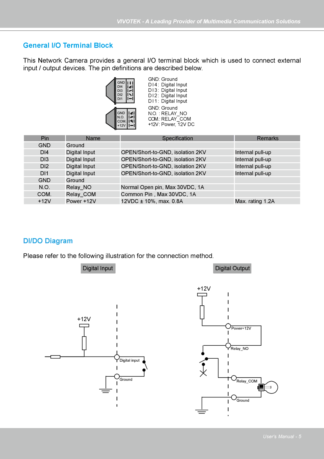
DI/DO Diagram
Please refer to the following illustration for the connection method.
Digital Input |
| Digital Output |
|
|
|
+12V
+12V
| Power+12V |
| Relay_NO |
Digital input |
|
Ground | Relay_COM |
| |
| Ground |
User's Manual - 5