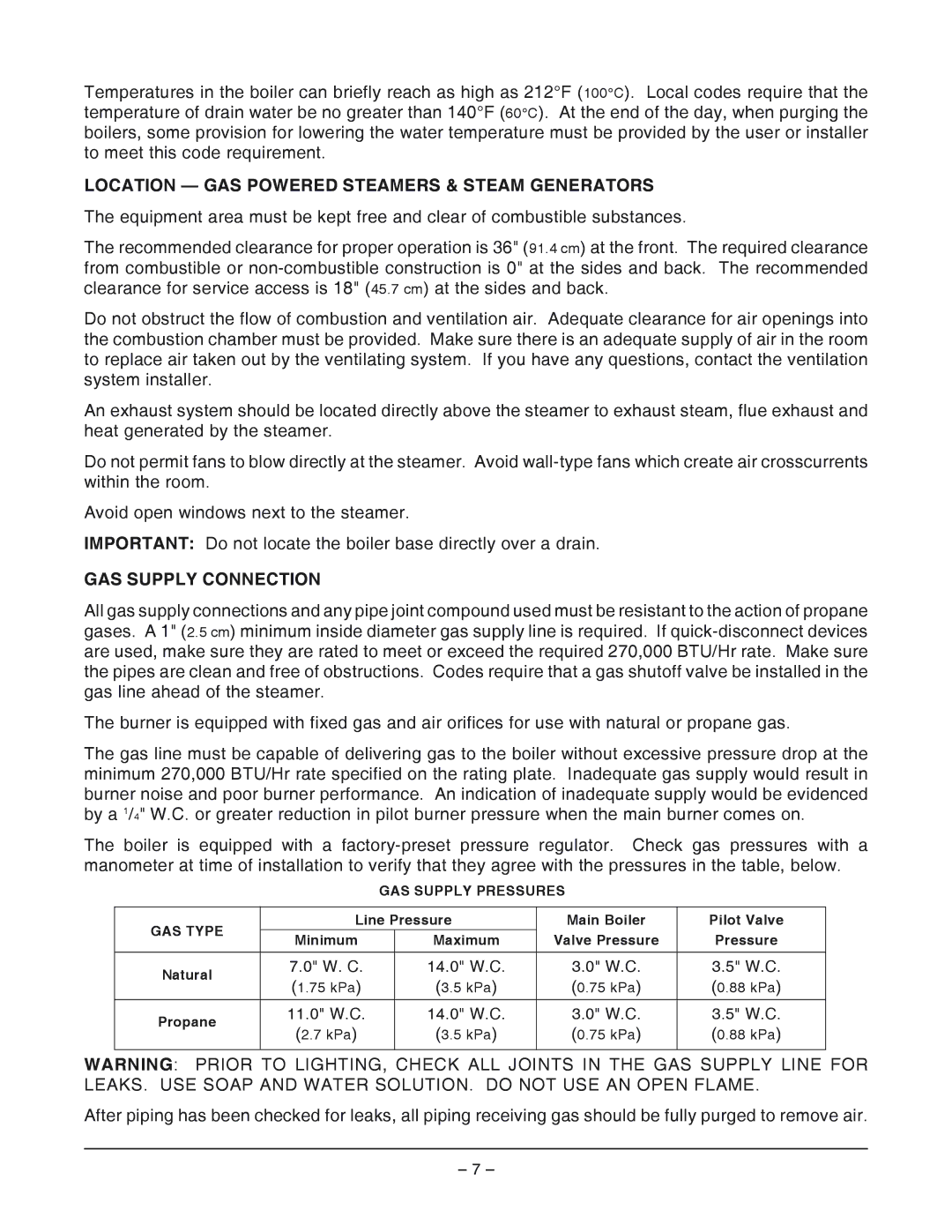
VHL3 & VH3616, VHL2, VHX24 specifications
Vulcan-Hart is renowned for its high-quality commercial cooking equipment, particularly in the foodservice industry. The VHX24, VHL2, VHL3, and VH3616 are standout models in their lineup, each offering unique features and technologies designed to meet the diverse needs of restaurants, cafeterias, and other food preparation settings.The Vulcan-Hart VHX24 is a powerful countertop convection oven that emphasizes efficiency and versatility. With a diverse cooking capacity, it can handle a variety of dishes simultaneously. It features a digital control panel that allows for precise temperature settings and cooking times, making it easier for chefs to achieve consistent results. This model also includes a stainless-steel exterior for easy cleaning and durability, making it a reliable choice in busy kitchens.
Moving on to the VHL2, this heavy-duty gas-fired broiler is engineered for high-volume grilling. It boasts dual burners that provide uniform heat distribution, ensuring that meat and vegetables are cooked evenly and to perfection. The VHL2 is also designed with a removable grease drawer, making maintenance straightforward and efficient. Its robust construction and large cooking surface make it an ideal choice for establishments that require extensive grilling capabilities.
The VHL3 takes the broiling experience a step further. This model includes three burners for enhanced cooking flexibility, allowing chefs to prepare larger quantities of food without sacrificing timing or quality. The VHL3 also features an adjustable grid and a high-efficiency radiant system, which reduces energy consumption while maintaining exceptional cooking performance. It’s perfect for busy kitchens that do not compromise on quality.
Finally, the VH3616 is a versatile, heavy-duty gas countertop fryer equipped to handle high-volume frying needs. It has a sizeable fry pot, making it suitable for cooking large batches of fries, chicken, and more. The VH3616 features a state-of-the-art temperature control system that ensures oil heats quickly and maintains consistent temperatures for optimal cooking results. Additionally, it includes a built-in filtration system that helps prolong the life of the oil and enhances food quality.
Together, the Vulcan-Hart VHX24, VHL2, VHL3, and VH3616 exemplify the brand's dedication to quality, innovation, and user-friendly design. Each model is tailored to support the demanding environments of commercial kitchens, providing chefs with the tools they need to create exceptional meals efficiently and consistently. Whether it’s baking, broiling, or frying, Vulcan-Hart continues to deliver reliable equipment that exceeds industry standards.

