www.vxitech.com
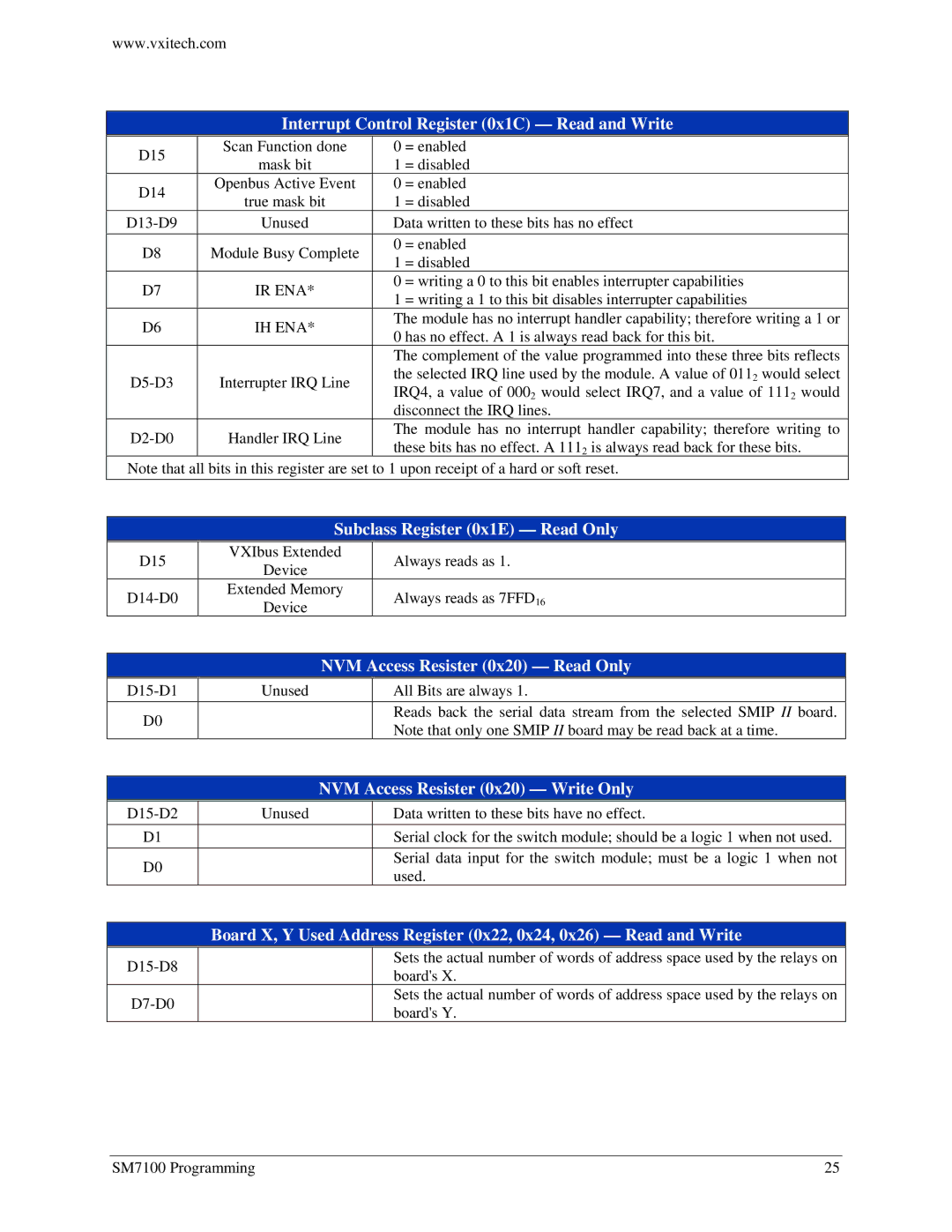
Interrupt Control Register (0x1C) — Read and Write
D15 | Scan Function done | 0 | = enabled | |
mask bit | 1 | = disabled | ||
| ||||
D14 | Openbus Active Event | 0 | = enabled | |
true mask bit | 1 | = disabled | ||
| ||||
Unused | Data written to these bits has no effect | |||
D8 | Module Busy Complete | 0 | = enabled | |
1 | = disabled | |||
|
| |||
D7 | IR ENA* | 0 | = writing a 0 to this bit enables interrupter capabilities | |
1 | = writing a 1 to this bit disables interrupter capabilities | |||
|
| |||
D6 | IH ENA* | The module has no interrupt handler capability; therefore writing a 1 or | ||
0 has no effect. A 1 is always read back for this bit. | ||||
|
| |||
|
| The complement of the value programmed into these three bits reflects | ||
Interrupter IRQ Line | the selected IRQ line used by the module. A value of 0112 would select | |||
IRQ4, a value of 0002 would select IRQ7, and a value of 1112 would | ||||
|
| |||
|
| disconnect the IRQ lines. | ||
Handler IRQ Line | The module has no interrupt handler capability; therefore writing to | |||
these bits has no effect. A 1112 is always read back for these bits. | ||||
|
| |||
Note that all bits in this register are set to 1 upon receipt of a hard or soft reset. | ||||
|
| Subclass Register (0x1E) — Read Only | |
| D15 | VXIbus Extended | Always reads as 1. |
| Device | ||
|
|
| |
| Extended Memory | Always reads as 7FFD16 | |
| Device | ||
|
|
| |
|
|
| NVM Access Resister (0x20) — Read Only | |
| Unused |
| All Bits are always 1. | |
| D0 |
|
| Reads back the serial data stream from the selected SMIP II board. |
|
|
| Note that only one SMIP II board may be read back at a time. | |
|
|
|
| |
|
|
| NVM Access Resister (0x20) — Write Only | |
| Unused |
| Data written to these bits have no effect. | |
| D1 |
|
| Serial clock for the switch module; should be a logic 1 when not used. |
| D0 |
|
| Serial data input for the switch module; must be a logic 1 when not |
|
|
| used. | |
|
|
|
| |
Board X, Y Used Address Register (0x22, 0x24, 0x26) — Read and Write
| Sets the actual number of words of address space used by the relays on | |
| board's X. | |
|
| |
| Sets the actual number of words of address space used by the relays on | |
| board's Y. | |
|
|
SM7100 Programming | 25 |