www.vxitech.com
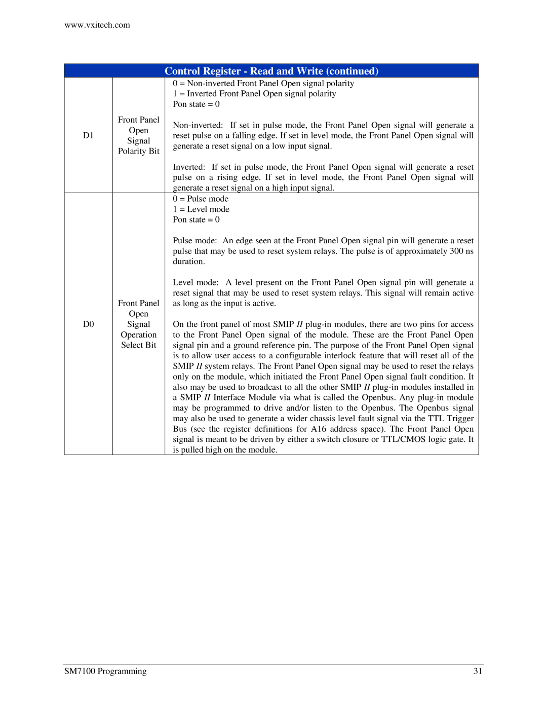
Control Register - Read and Write (continued)
0=
1= Inverted Front Panel Open signal polarity Pon state = 0
| Front Panel | ||
D1 | Open | ||
reset pulse on a falling edge. If set in level mode, the Front Panel Open signal will | |||
Signal | |||
| generate a reset signal on a low input signal. | ||
| Polarity Bit | ||
|
| ||
|
| Inverted: If set in pulse mode, the Front Panel Open signal will generate a reset | |
|
| pulse on a rising edge. If set in level mode, the Front Panel Open signal will | |
|
| generate a reset signal on a high input signal. | |
|
| 0 = Pulse mode | |
|
| 1 = Level mode | |
|
| Pon state = 0 | |
|
| Pulse mode: An edge seen at the Front Panel Open signal pin will generate a reset | |
|
| pulse that may be used to reset system relays. The pulse is of approximately 300 ns | |
|
| duration. | |
|
| Level mode: A level present on the Front Panel Open signal pin will generate a | |
| Front Panel | reset signal that may be used to reset system relays. This signal will remain active | |
| as long as the input is active. | ||
D0 | Open | On the front panel of most SMIP II | |
Signal | |||
| Operation | to the Front Panel Open signal of the module. These are the Front Panel Open | |
| Select Bit | signal pin and a ground reference pin. The purpose of the Front Panel Open signal | |
|
| is to allow user access to a configurable interlock feature that will reset all of the | |
|
| SMIP II system relays. The Front Panel Open signal may be used to reset the relays | |
|
| only on the module, which initiated the Front Panel Open signal fault condition. It | |
|
| also may be used to broadcast to all the other SMIP II | |
|
| a SMIP II Interface Module via what is called the Openbus. Any | |
|
| may be programmed to drive and/or listen to the Openbus. The Openbus signal | |
|
| may also be used to generate a wider chassis level fault signal via the TTL Trigger | |
|
| Bus (see the register definitions for A16 address space). The Front Panel Open | |
|
| signal is meant to be driven by either a switch closure or TTL/CMOS logic gate. It | |
|
| is pulled high on the module. |
SM7100 Programming | 31 |