VXI Technology, Inc.
Delay Register - Read and Write
ADDR | |||
|
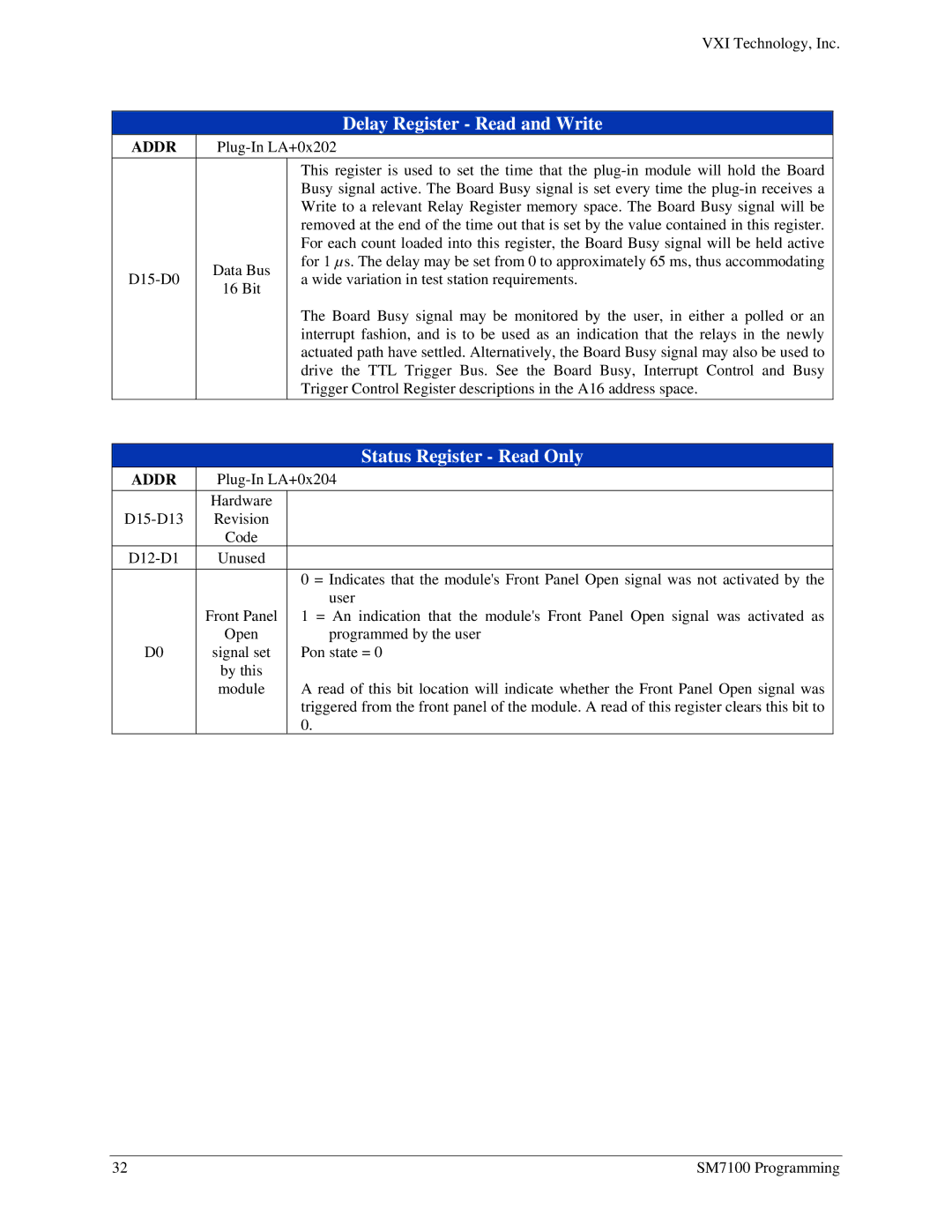
| This register is used to set the time that the | |
|
| Busy signal active. The Board Busy signal is set every time the | |
|
| Write to a relevant Relay Register memory space. The Board Busy signal will be | |
|
| removed at the end of the time out that is set by the value contained in this register. | |
|
| For each count loaded into this register, the Board Busy signal will be held active | |
Data Bus | for 1 µs. The delay may be set from 0 to approximately 65 ms, thus accommodating | ||
a wide variation in test station requirements. | |||
16 Bit | |||
|
| ||
|
| The Board Busy signal may be monitored by the user, in either a polled or an | |
|
| interrupt fashion, and is to be used as an indication that the relays in the newly | |
|
| actuated path have settled. Alternatively, the Board Busy signal may also be used to | |
|
| drive the TTL Trigger Bus. See the Board Busy, Interrupt Control and Busy | |
|
| Trigger Control Register descriptions in the A16 address space. | |
Status Register - Read Only
ADDR | ||
| Hardware |
|
Revision |
| |
| Code |
|
Unused |
| |
|
| 0 = Indicates that the module's Front Panel Open signal was not activated by the |
| Front Panel | user |
| 1 = An indication that the module's Front Panel Open signal was activated as | |
D0 | Open | programmed by the user |
signal set | Pon state = 0 | |
| by this |
|
| module | A read of this bit location will indicate whether the Front Panel Open signal was |
|
| triggered from the front panel of the module. A read of this register clears this bit to |
|
| 0. |
32 | SM7100 Programming |
