VXI Technology, Inc.
Control Register - Read and Write (continued)
|
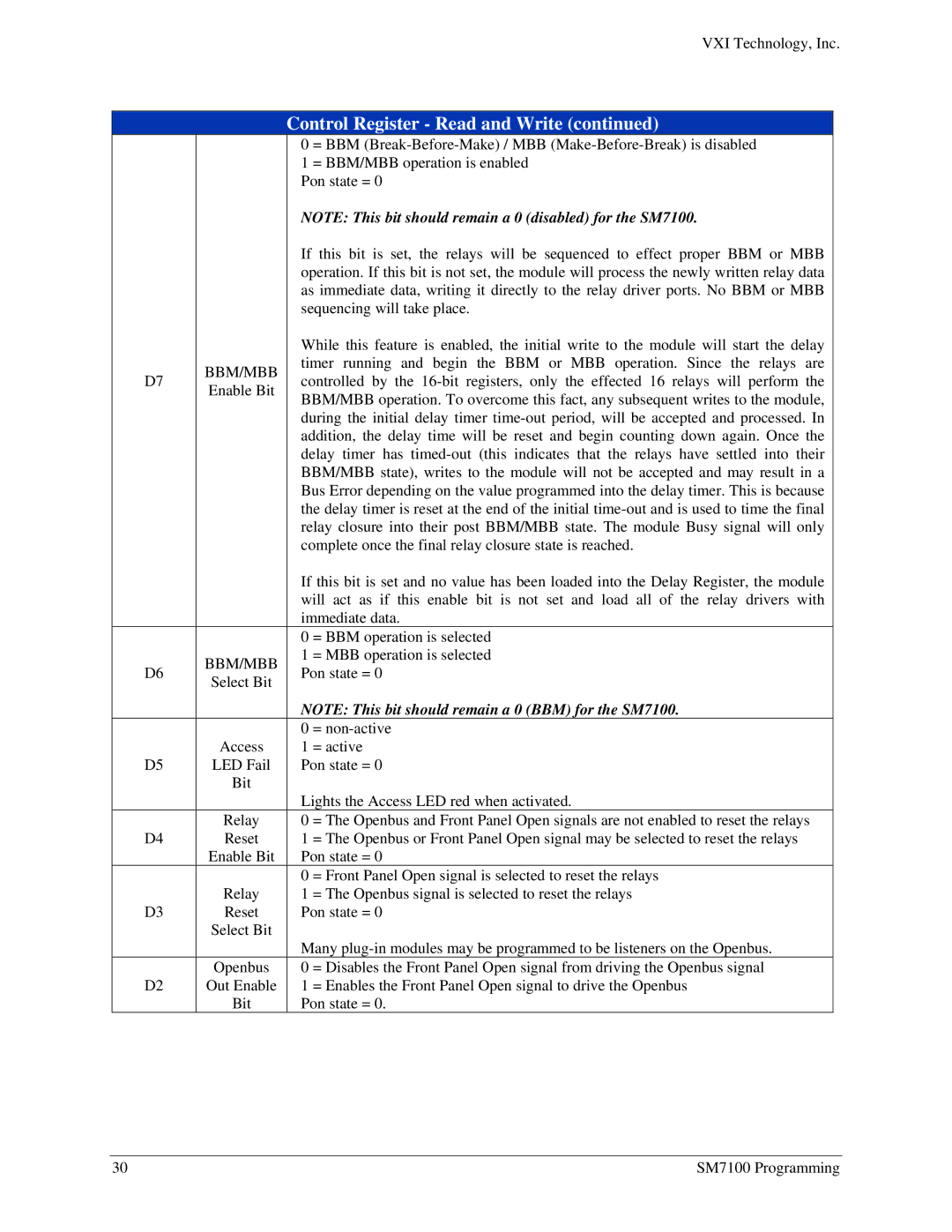
| 0 | = BBM | |||
|
| 1 | = BBM/MBB operation is enabled |
| ||
|
| Pon state = 0 |
|
| ||
|
| NOTE: This bit should remain a 0 (disabled) for the SM7100. | ||||
|
| If this bit is set, the relays will be sequenced to effect proper BBM or MBB | ||||
|
| operation. If this bit is not set, the module will process the newly written relay data | ||||
|
| as immediate data, writing it directly to the relay driver ports. No BBM or MBB | ||||
|
| sequencing will take place. |
| |||
|
| While this feature is enabled, the initial write to the module will start the delay | ||||
D7 | BBM/MBB | timer running | and begin the BBM or | MBB operation. Since the relays are | ||
controlled by | the | the effected 16 relays will perform the | ||||
Enable Bit | ||||||
| BBM/MBB operation. To overcome this fact, any subsequent writes to the module, | |||||
|
| |||||
|
| during the initial delay timer | ||||
|
| addition, the delay time will be reset and begin counting down again. Once the | ||||
|
| delay timer has | ||||
|
| BBM/MBB state), writes to the module will not be accepted and may result in a | ||||
|
| Bus Error depending on the value programmed into the delay timer. This is because | ||||
|
| the delay timer is reset at the end of the initial | ||||
|
| relay closure into their post BBM/MBB state. The module Busy signal will only | ||||
|
| complete once the final relay closure state is reached. | ||||
|
| If this bit is set and no value has been loaded into the Delay Register, the module | ||||
|
| will act as if this enable bit is not set and load all of the relay drivers with | ||||
|
| immediate data. |
| |||
|
| 0 | = BBM operation is selected |
| ||
D6 | BBM/MBB | 1 | = MBB operation is selected |
| ||
Pon state = 0 |
|
| ||||
Select Bit |
|
| ||||
|
|
|
|
| ||
|
| NOTE: This bit should remain a 0 (BBM) for the SM7100. | ||||
| Access | 0 | = |
|
| |
| 1 | = active |
|
| ||
D5 | LED Fail | Pon state = 0 |
|
| ||
| Bit | Lights the Access LED red when activated. | ||||
|
| |||||
| Relay | 0 | = The Openbus and Front Panel Open signals are not enabled to reset the relays | |||
D4 | Reset | 1 | = The Openbus or Front Panel Open signal may be selected to reset the relays | |||
| Enable Bit | Pon state = 0 |
|
| ||
| Relay | 0 | = Front Panel Open signal is selected to reset the relays | |||
| 1 | = The Openbus signal is selected to reset the relays | ||||
D3 | Reset | Pon state = 0 |
|
| ||
| Select Bit | Many | ||||
|
| |||||
| Openbus | 0 | = Disables the Front Panel Open signal from driving the Openbus signal | |||
D2 | Out Enable | 1 | = Enables the Front Panel Open signal to drive the Openbus | |||
| Bit | Pon state = 0. |
|
| ||
30 | SM7100 Programming |
