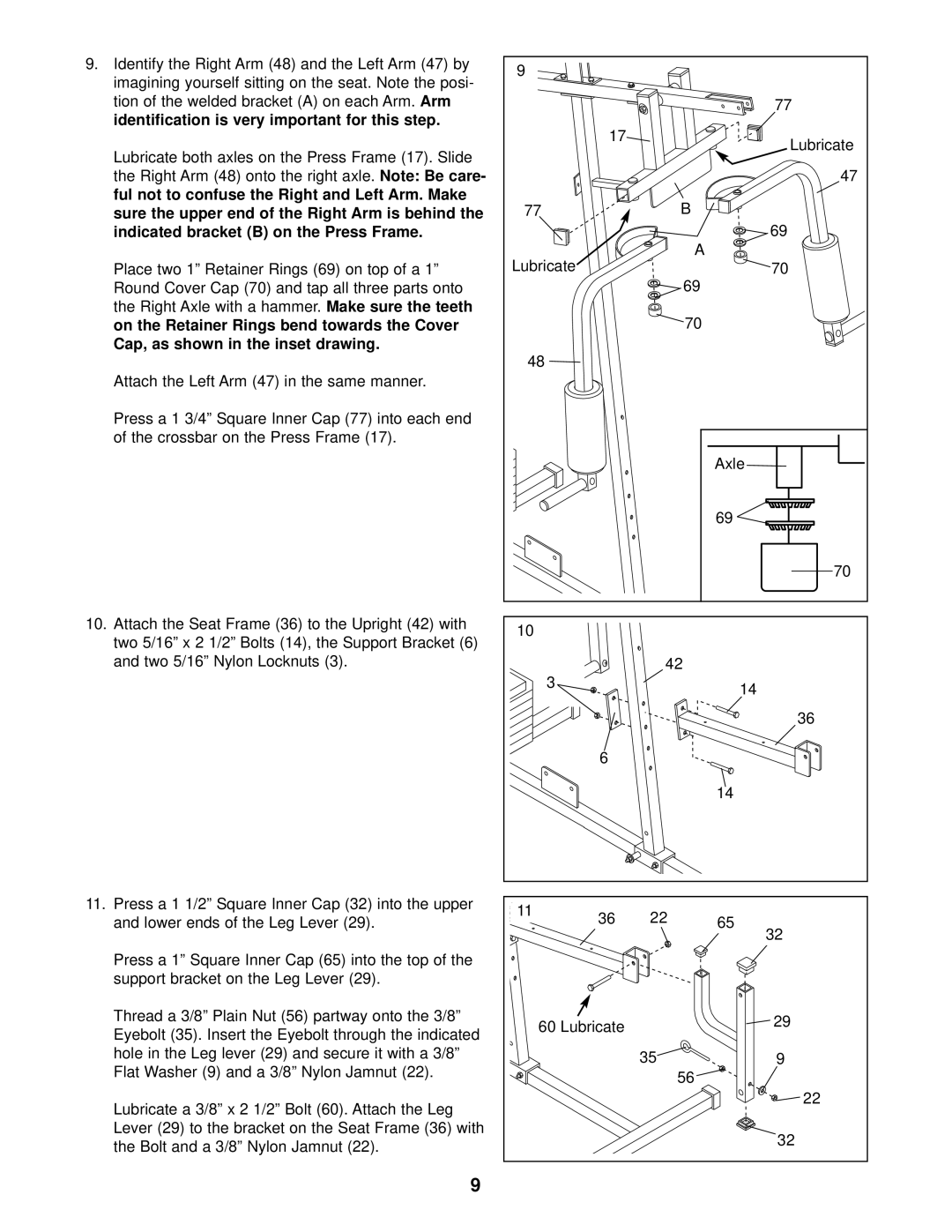
9.Identify the Right Arm (48) and the Left Arm (47) by imagining yourself sitting on the seat. Note the posi-
tion of the welded bracket (A) on each Arm. | Arm |
identification is very important for this step. |
|
Lubricate both axles on the Press Frame (17). Slide
the Right Arm (48) onto the right axle. Note: Be care- ful not to confuse the Right and Left Arm. Make
sure the upper end of the Right Arm is behind the indicated bracket (B) on the Press Frame.
Place two 1” Retainer Rings (69) on top of a 1” Round Cover Cap (70) and tap all three parts onto
the Right Axle with a hammer. Make sure the teeth
on the Retainer Rings bend towards the Cover Cap, as shown in the inset drawing.
Attach the Left Arm (47) in the same manner.
Press a 1 3/4” Square Inner Cap (77) into each end of the crossbar on the Press Frame (17).
10.Attach the Seat Frame (36) to the Upright (42) with
two 5/16” x 2 1/2” Bolts (14), the Support Bracket (6) and two 5/16” Nylon Locknuts (3).
11.Press a 1 1/2” Square Inner Cap (32) into the upper and lower ends of the Leg Lever (29).
Press a 1” Square Inner Cap (65) into the top of the support bracket on the Leg Lever (29).
Thread a 3/8” Plain Nut (56) partway onto the 3/8” Eyebolt (35). Insert the Eyebolt through the indicated hole in the Leg lever (29) and secure it with a 3/8” Flat Washer (9) and a 3/8” Nylon Jamnut (22).
Lubricate a 3/8” x 2 1/2” Bolt (60). Attach the Leg Lever (29) to the bracket on the Seat Frame (36) with the Bolt and a 3/8” Nylon Jamnut (22).
9
9 |
|
|
|
|
|
| 77 |
| 17 |
| Lubricate |
|
|
| |
|
|
| 47 |
77 |
|
| B |
|
|
| 69 |
Lubricate |
|
| A |
|
| 70 | |
|
|
| 69 |
|
|
| 70 |
48 |
|
|
|
|
|
| Axle |
|
|
| 69 |
|
|
| 70 |
10 |
|
|
|
|
|
| 42 |
3 |
|
| 14 |
|
|
| |
|
|
| 36 |
| 6 |
|
|
|
|
| 14 |
11 | 36 | 22 | 65 |
| |||
|
|
| 32 |
60 Lubricate |
| 29 | |
|
| ||
35 ![]() 9
9
56![]()
![]() 22
22
32