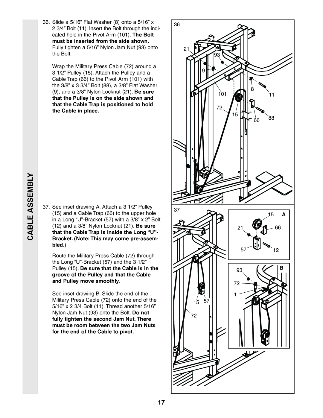
36. Slide a 5/16” Flat Washer (8) onto a 5/16” x |
2 3/4” Bolt (11). Insert the Bolt through the indi- |
cated hole in the Pivot Arm (101). The Bolt |
must be inserted from the side shown. |
36
Fully tighten a 5/16” Nylon Jam Nut (93) onto |
the Bolt. |
Wrap the Military Press Cable (72) around a |
3 1/2” Pulley (15). Attach the Pulley and a |
Cable Trap (66) to the Pivot Arm (101) with |
the 3/8” x 3 3/4” Bolt (88), a 3/8” Flat Washer |
(9), and a 3/8” Nylon Locknut (21). Be sure |
that the Pulley is on the side shown and |
that the Cable Trap is positioned to hold |
the Cable in place. |
21
93 |
9
101
72
15
8
|
|
| 11 | |||
|
|
|
|
|
|
|
|
|
|
|
|
|
|
|
|
|
|
|
|
|
|
|
|
|
|
|
|
|
|
|
|
| ||
|
| 88 | ||||
66 |
|
|
| |||
|
|
|
|
| ||
|
|
|
|
|
|
|
CABLE ASSEMBLY
37.See inset drawing A. Attach a 3 1/2” Pulley
(15)and a Cable Trap (66) to the upper hole in a Long
(12)and a 3/8” Nylon Locknut (21). Be sure that the Cable Trap is inside the Long “U”- Bracket. (Note: This may come
Route the Military Press Cable (72) through the Long
See inset drawing B. Slide the end of the Military Press Cable (72) onto the end of the 5/16” x 2 3/4 Bolt (11). Thread another 5/16” Nylon Jam Nut (93) onto the Bolt. Do not fully tighten the second Jam Nut. There must be room between the two Jam Nuts for the end of the Cable to pivot.
37
15 | A |
21 | 66 |
57 | 12 |
|
|
| B |
93 |
|
| |
| |||
|
|
| |
|
|
|
|
|
|
|
|
72 |
![]() 1 15 57
1 15 57
72
17