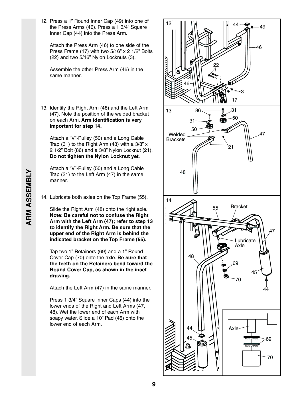
12.Press a 1” Round Inner Cap (49) into one of the Press Arms (46). Press a 1 3/4” Square Inner Cap (44) into the Press Arm.
Attach the Press Arm (46) to one side of the Press Frame (17) with two 5/16” x 2 1/2” Bolts (22) and two 5/16” Nylon Locknuts (3).
Assemble the other Press Arm (46) in the same manner.
12 | 44 | 49 |
|
|
46
22 |
46 |
3
17
13. Identify the Right Arm (48) and the Left Arm |
(47). Note the position of the welded bracket |
on each Arm. Arm identification is very |
important for step 14. |
Attach a |
Trap (31) to the Right Arm (48) with a 3/8” x |
2 1/2” Bolt (86) and a 3/8” Nylon Locknut (21). |
Do not tighten the Nylon Locknut yet. |
Attach a |
13 | 86 |
31
50
Welded
Brackets
31
50
47
21
ARM ASSEMBLY
Trap (31) to the Left Arm (47) in the same |
manner. |
14. Lubricate both axles on the Top Frame (55). |
Slide the Right Arm (48) onto the right axle. |
Note: Be careful not to confuse the Right |
Arm with the Left Arm (47); refer to step 13 |
to identify the Right Arm. Be sure that the |
upper end of the Right Arm is behind the |
indicated bracket on the Top Frame (55). |
Tap two 1” Retainers (69) and a 1” Round |
Cover Cap (70) onto the axle. Be sure that |
the teeth on the Retainers bend toward the |
Round Cover Cap, as shown in the inset |
drawing. |
Attach the Left Arm (47) in the same manner. |
Press 1 3/4” Square Inner Caps (44) into the |
lower ends of the Right and Left Arms (47, |
48). Wet the lower end of each Arm with |
soapy water. Slide a 10” Pad (45) onto the |
lower end of each Arm. |
48
14
55 Bracket
47
Lubricate
Axle
48
69
45
70
44
44 |
|
| Axle |
|
45 | 69 |
| 70 |
9