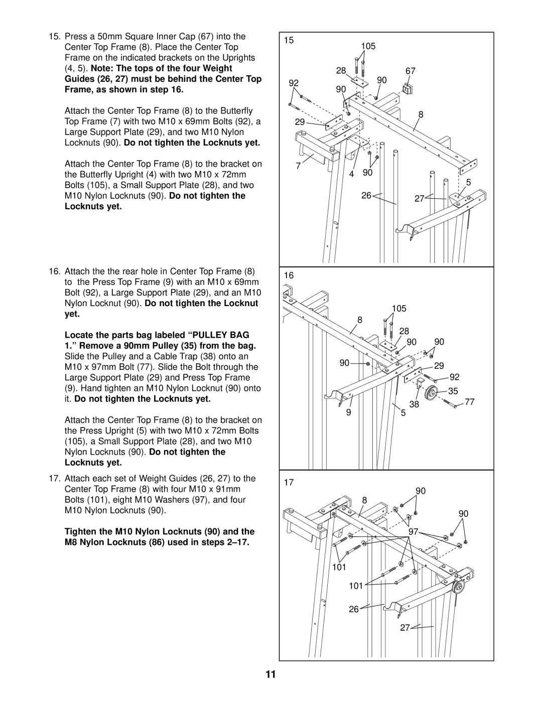
15. Press a 50mm Square Inner Cap (67) into the | 15 | 105 |
|
|
Center Top Frame (8). Place the Center Top |
|
| ||
|
|
| ||
Frame on the indicated brackets on the Uprights |
|
|
|
|
(4, 5). Note: The tops of the four Weight | 28 |
| 67 |
|
Guides (26, 27) must be behind the Center Top |
|
| ||
92 |
| 90 |
| |
Frame, as shown in step 16. |
|
|
| |
90 |
|
|
| |
Attach the Center Top Frame (8) to the Butterfly |
|
| 8 |
|
Top Frame (7) with two M10 x 69mm Bolts (92), a | 29 |
|
| |
|
|
| ||
Large Support Plate (29), and two M10 Nylon |
|
|
|
|
Locknuts (90). Do not tighten the Locknuts yet. |
|
|
|
|
Attach the Center Top Frame (8) to the bracket on | 7 | 90 |
|
|
the Butterfly Upright (4) with two M10 x 72mm | 4 |
| 5 | |
Bolts (105), a Small Support Plate (28), and two |
|
|
| |
|
|
|
| |
M10 Nylon Locknuts (90). Do not tighten the |
| 26 | 27 |
|
Locknuts yet. |
|
|
| |
|
|
|
| |
16. Attach the the rear hole in Center Top Frame (8) | 16 |
|
|
|
to the Press Top Frame (9) with an M10 x 69mm |
|
|
| |
|
|
|
| |
Bolt (92), a Large Support Plate (29), and an M10 |
|
|
|
|
Nylon Locknut (90). Do not tighten the Locknut |
|
| 105 |
|
yet. |
|
|
| |
| 8 |
|
| |
|
|
|
| |
Locate the parts bag labeled “PULLEY BAG |
|
| 28 |
|
|
| 90 | 90 | |
1.” Remove a 90mm Pulley (35) from the bag. |
|
| ||
|
|
|
| |
Slide the Pulley and a Cable Trap (38) onto an | 90 |
|
| 29 |
M10 x 97mm Bolt (77). Slide the Bolt through the |
|
| ||
|
|
| ||
Large Support Plate (29) and Press Top Frame |
|
|
| 92 |
(9). Hand tighten an M10 Nylon Locknut (90) onto |
|
|
| 35 |
it. Do not tighten the Locknuts yet. |
|
|
| |
|
| 38 | 77 | |
| 9 |
| ||
Attach the Center Top Frame (8) to the bracket on |
| 5 |
| |
|
|
|
| |
the Press Upright (5) with two M10 x 72mm Bolts |
|
|
|
|
(105), a Small Support Plate (28), and two M10 |
|
|
|
|
Nylon Locknuts (90). Do not tighten the |
|
|
|
|
Locknuts yet. |
|
|
|
|
17. Attach each set of Weight Guides (26, 27) to the | 17 |
|
|
|
Center Top Frame (8) with four M10 x 91mm |
| 90 |
| |
|
|
| ||
Bolts (101), eight M10 Washers (97), and four |
| 8 |
|
|
M10 Nylon Locknuts (90). |
|
|
| 90 |
|
|
|
| |
Tighten the M10 Nylon Locknuts (90) and the |
|
| 97 |
|
M8 Nylon Locknuts (86) used in steps |
|
|
|
|
| 101 |
|
|
|
| 101 |
|
| |
| 26 |
|
| |
|
|
| 27 |
|
11
