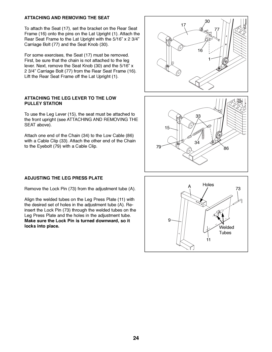
ATTACHING AND REMOVING THE SEAT
To attach the Seat (17), set the bracket on the Rear Seat Frame (16) onto the pins on the Lat Upright (1). Attach the Rear Seat Frame to the Lat Upright with the 5/16Ó x 2 3/4Ó Carriage Bolt (77) and the Seat Knob (30).
For some exercises, the Seat (17) must be removed. First, be sure that the chain is not attached to the leg lever. Next, remove the Seat Knob (30) and the 5/16Ó x
2 3/4Ó Carriage Bolt (77) from the Rear Seat Frame (16). Lift the Rear Seat Frame off the Lat Upright (1).
ATTACHING THE LEG LEVER TO THE LOW PULLEY STATION
To use the Leg Lever (15), the seat must be attached to the front upright (see ATTACHING AND REMOVING THE SEAT above).
Attach one end of the Chain (34) to the Low Cable (86) with a Cable Clip (33). Attach the other end of the Chain to the Eyebolt (79) with a Cable Clip.
ADJUSTING THE LEG PRESS PLATE
Remove the Lock Pin (73) from the adjustment tube (A).
Align the welded tubes on the Leg Press Plate (11) with the desired set of holes in the adjustment tube (A). Re- insert the Lock Pin (73) through the welded tubes on the Leg Press Plate and the holes in the adjustment tube.
Make sure the Lock Pin is turned downward, so it locks into place.
| 17 | 30 |
| 77 | |
|
| |
|
| 16 |
|
| 1 |
|
| 33 |
| 15 |
|
79 |
| 34 |
| 86 | |
|
| |
| A | Holes |
| 73 | |
|
| |
| 9 |
|
|
| Welded |
|
| Tubes |
|
| 11 |
24