PLUS-E017-A/1206 specifications
The Weil-McLain PLUS-E017-A/1206 is a high-performance heating boiler that reflects the brand's commitment to quality engineering and advanced technology. This model is renowned for its efficiency and reliability, making it a preferred choice for both residential and commercial heating applications.One of the standout features of the PLUS-E017-A/1206 is its exceptional efficiency rating. The boiler employs advanced condensing technology, which allows it to utilize the latent heat in exhaust gases. This means it can achieve efficiency levels of over 90%, significantly reducing energy consumption and lowering utility bills. The unit also complies with stringent regulatory standards, making it an environmentally friendly heating solution.
The PLUS-E017-A/1206's compact design is another significant characteristic, allowing for easy installation even in limited spaces. It is built with durable materials that enhance its longevity and efficiency. The sleek appearance of the unit also makes it suitable for various settings, maintaining aesthetic appeal while delivering powerful heating performance.
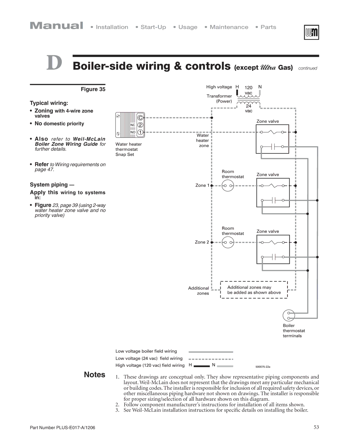
This boiler is equipped with advanced controls and a user-friendly interface, offering precise temperature management and efficient operation. The control panel showcases a digital display, enabling easy monitoring of system performance. Additionally, it allows for integration with smart home systems, providing users with enhanced control over their heating systems remotely.
Safety features are paramount in the PLUS-E017-A/1206. It includes multiple safety mechanisms designed to prevent overheating and pressure issues, ensuring worry-free operation. These elements, combined with Weil-McLain’s reputation for durable construction, contribute to the boiler’s overall reliability.
The PLUS-E017-A/1206 is designed with ease of maintenance in mind. It features accessible components that can be easily serviced, minimizing downtime and reducing maintenance costs. With Weil-McLain’s extensive network of support, users can rely on expert assistance when needed.
Overall, the Weil-McLain PLUS-E017-A/1206 is a robust heating solution that combines efficiency, safety, and advanced technology. Its range of features makes it an excellent choice for those seeking a dependable boiler that delivers consistent performance and energy savings. Whether for a home or business, the PLUS-E017-A/1206 represents a smart investment in heating technology.

