Component Testing Information
!WARNING
To avoid the risk of electrical shock, personal injury, or death, disconnect power to unit before servicing, unless testing requires power.
Mechanical Controls
Illustration | Component | Test Procedure | Results |
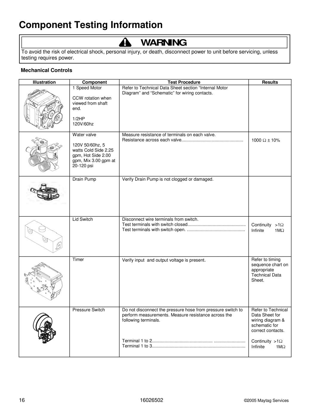
| 1 Speed Motor | Refer to Technical Data Sheet section “Internal Motor |
|
|
| Diagram” and “Schematic” for wiring contacts. |
|
CCW rotation when viewed from shaft end.
1/2HP |
|
|
120V/60hz |
|
|
|
|
|
Water valve | Measure resistance of terminals on each valve. |
|
120V 50/60hz, 5 | Resistance across each valve | 1000 Ω ± 10% |
|
| |
watts Cold Side 2.25 |
|
|
gpm, Hot Side 2.00 |
|
|
gpm, Mix 3.00 gpm at |
|
|
|
| |
|
|
|
Drain Pump | Verify Drain Pump is not clogged or damaged. |
|
Lid Switch | Disconnect wire terminals from switch. |
|
|
| Test terminals with switch closed | Continuity | >1Ω |
| Test terminals with switch open | Infinite | Ω |
|
| 1M |
Timer | Verify input and output voltage is present. | Refer to timing |
|
| sequence chart on |
|
| appropriate |
|
| Technical Data |
|
| Sheet. |
Pressure Switch | Do not disconnect the pressure hose from pressure switch to | Refer to Technical | |
| perform measurements. Measure resistance across the | Data Sheet for | |
| following terminals. | wiring diagram & | |
|
| schematic for | |
|
| correct contacts. | |
| Terminal 1 to 2 | Continuity | >1Ω |
| Terminal 1 to 3 | Infinite | Ω |
|
| 1M | |
16 | 16026502 | ©2005 Maytag Services |