Disassembly Procedures
!WARNING
To avoid risk of electrical shock, personal injury or death, disconnect power to unit before servicing.
4. Remove screws retaining the Tub Seal.
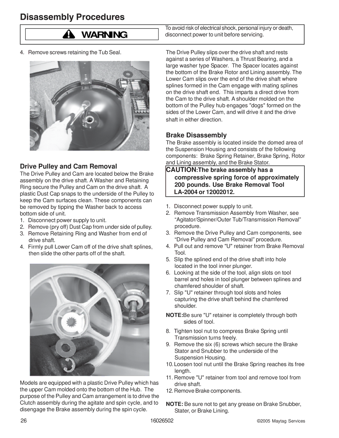
Drive Pulley and Cam Removal
The Drive Pulley and Cam are located below the Brake assembly on the drive shaft. A Washer and Retaining Ring secure the Pulley and Cam on the drive shaft. A plastic Dust Cap snaps to the underside of the Pulley to keep the Cam surfaces clean. These components can be removed by tipping the Washer back to access bottom side of unit.
1.Disconnect power supply to unit.
2.Remove (pry off) Dust Cap from under side of pulley.
3.Remove Retaining Ring and Washer from end of drive shaft.
4.Firmly pull Lower Cam off of the drive shaft splines, then slide the other parts off of the shaft.
Models are equipped with a plastic Drive Pulley which has the upper Cam molded onto the bottom of the Hub. The purpose of the Pulley and Cam arrangement is to drive the Clutch assembly during the agitate and spin cycle, and to disengage the Brake assembly during the spin cycle.
The Drive Pulley slips over the drive shaft and rests against a series of Washers, a Thrust Bearing, and a large washer type Spacer. The Spacer locates against the bottom of the Brake Rotor and Lining assembly. The Lower Cam slips over the end of the drive shaft where splines formed in the Cam engage with mating splines on the drive shaft end. This imparts a direct drive from the Cam to the drive shaft. A shoulder molded on the bottom of the Pulley hub engages "dogs" formed on the sides of the Lower Cam, and will drive it and the drive
shaft in either direction.
Brake Disassembly
The Brake assembly is located inside the domed area of the Suspension Housing and consists of the following components: Brake Spring Retainer, Brake Spring, Rotor and Lining assembly, and the Brake Stator.
CAUTION:The brake assembly has a compressive spring force of approximately 200 pounds. Use Brake Removal Tool
1.Disconnect power supply to unit.
2.Remove Transmission Assembly from Washer, see “Agitator/Spinner/Outer Tub/Transmission Removal” procedure.
3.Remove the Drive Pulley and Cam components, see “Drive Pulley and Cam Removal” procedure.
4.Pull out and remove "U" retainer from Brake Removal Tool.
5.Slip the splined end of the drive shaft into hole located in the tool inner plunger.
6.Looking at the side of the tool, align slots on tool barrel and holes in tool plunger between splines and chamfered shoulder of shaft.
7.Slip "U" retainer through tool slots and holes capturing the drive shaft behind the chamfered shoulder.
NOTE:Be sure "U" retainer is completely through both sides of tool.
8.Tighten tool nut to compress Brake Spring until Transmission turns freely.
9.Remove the six (6) screws which secure the Brake Stator and Snubber to the underside of the Suspension Housing.
10.Loosen tool nut until the Brake Spring reaches its free length.
11.Remove "U" retainer from tool and remove tool from drive shaft.
12.Remove Brake components.
NOTE: Be sure not to get any grease on Brake Snubber, Stater, or Brake Lining.
26 | 16026502 | ©2005 Maytag Services |