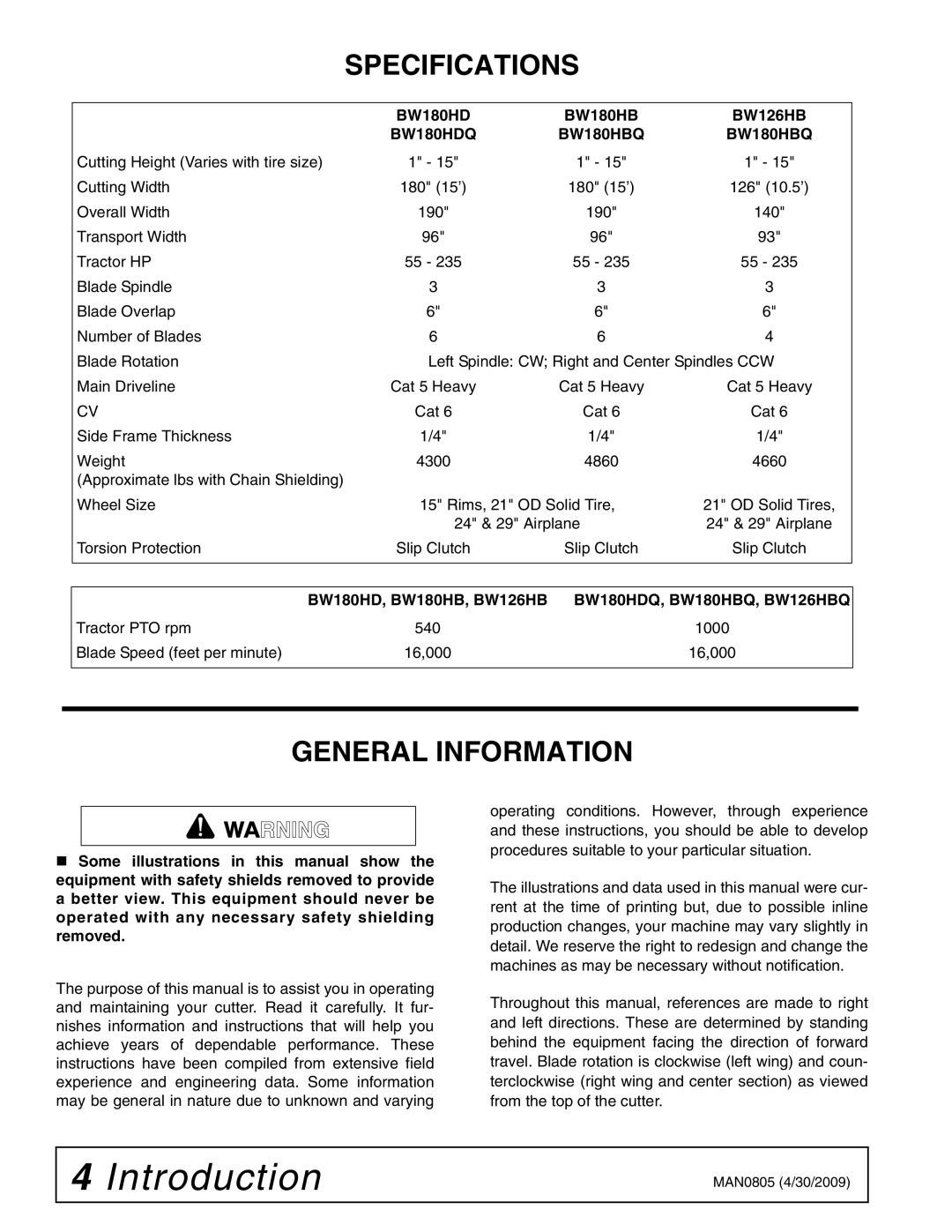
BW180HDQ, BW180HD, BW180HB specifications
Woods Equipment has long been a leader in the agricultural and landscaping industry, providing exceptional products that enhance productivity and efficiency. Among its standout offerings are the BW180HB, BW180HD, and BW180HDQ models. These versatile implements are primarily designed for use with tractors, making them invaluable for a variety of tasks.The BW180HB model is known for its high-performance capabilities combined with a compact design. One of its main features is its heavy-duty construction, which ensures durability and longevity even under strenuous conditions. The implement is equipped with a balanced weight distribution system that allows for better stability and control during operation. Additionally, the BW180HB is designed to handle a range of tasks from grading and leveling to scraping and light dozing.
Moving up the series, the BW180HD offers a higher capacity and is built for more demanding applications. This model features a robust hydraulic system that enhances lifting capabilities, allowing operators to tackle heavier loads with ease. Its advanced blade adjustment features allow for precise angle and depth control, making it ideal for a variety of terrains. The BW180HD is particularly praised for its reliability in tough environments, thanks to its reinforced frame and high-quality materials.
The BW180HDQ model represents the pinnacle of Woods Equipment's offerings in this series. It features all the capabilities of the BW180HD but includes advanced technological enhancements for improved performance. The inclusion of an automated hydraulic control system streamlines operations, enabling operators to adjust settings on-the-fly to adapt to changing conditions. Additionally, the BW180HDQ comes with integrated safety features that protect both the operator and the equipment during use.
All three models share several common characteristics that make them preferred choices among landscaping and construction professionals. They are compatible with a wide range of tractor types, ensuring versatility for various users. The quick-connect attachment points allow for rapid changes between implements, saving time and increasing productivity. With easy maintenance designs, these models ensure that downtime is minimized, allowing operators to focus on the task at hand.
In summary, the Woods Equipment BW180HB, BW180HD, and BW180HDQ models are exceptional tools for anyone looking to enhance their operational efficiency in agriculture or landscaping. With their robust features, advanced technologies, and commitment to durability, these implements represent some of the best options available in the market today.

