20 PLANER
INSTRUCTION MANUAL
MODEL W1683
COPYRIGHT April, 2002 BY WOODSTOCK INTERNATIONAL, INC
INSTRUCTION SHEET
Spiral Cutterhead Planer
Model W1718
INTRODUCTION
W1718 Replacement Parts
Lead from lead-based paints
Crystalline silica from bricks, cement, and other masonry products
Arsenic and chromium from chemically treated lumber
Table Of Contents
WOODSTOCK SERVICE AND SUPPORT
WARRANTY AND RETURNS
PLANER MACHINE SPECIFICATIONS
WOODSTOCK SERVICE AND SUPPORT
INTRODUCTION ABOUT YOUR NEW PLANER
WARRANTY AND RETURNS
Planer Machine Specifications
5 H.P., 220V, Single-Phase
Motor
SAFETY FIRST
11. Disconnect machine when cleaning, adjusting or servicing
6. Ensure all guards are securely in place and in working condition
READ MANUAL BEFORE OPERATING MACHINE
17. Keep proper footing and balance at all times
Read the manual
ADDITIONAL SAFETY INSTRUCTIONS FOR PLANERS
ELECTRICAL REQUIREMENTS
220V Operation
Extension Cords
Grounding
ASSEMBLY
Box Contents
Do not connect the machine to power at this time. The machine must
Overview
The Model W1683 is a heavy machine, 840 lbs. shipping weight. Use
when assembling, adjusting or operating equipment
Shop Preparation
Cleaning Machine
Extension Rollers
To install the dust hood
Handwheel
Dust Hood
To mount the handwheel
Switch
Knife Setting Jig
To mount the switch
To assemble the knife setting jig
ADJUSTMENTS
Location of Controls
Moving Bed Rollers
To move the bed rollers
To check the table 1. Make sure machine is unplugged
To adjust the table less than
To adjust the table more than
to ensure accurate results
Checking Knives
To check the knives
Knife Adjustment
To adjust the knives using the springs
1. Unplug the machine from the power source
To adjust the knives using the jack screws
To tighten the knives after adjustment
1 3 5 6 4
Figure 18. Gib bolt tightening sequence
To adjust the feed rollers, the chip breaker and the pressure bar
Feed Rollers, Chip Breaker & Pressure Bar
1. Unplug the machine from the power source
Figure 22. Chipbreaker adjustment controls
Figure 23. Pressure bar adjustment controls
Chip Deflector
Anti-Kickback Pawls
planer. To adjust the roller spring tension
Chain Tensioner
Spring Tension
more details
To adjust the table roller height
Table Rollers
safety
Operations
Test Run
Feed Rate
Operational Tips
Troubleshooting Planing Results
AFTERMARKET SETUP ACCESSORIES
Here are some basic aftermarket items you might want to consider
MAINTENANCE
Cleaning
General
Table And Base
Lubrication
Figure 37. Worm gear
Belt Tension
Pulley Alignment
To align the pulleys
Wiring Diagram
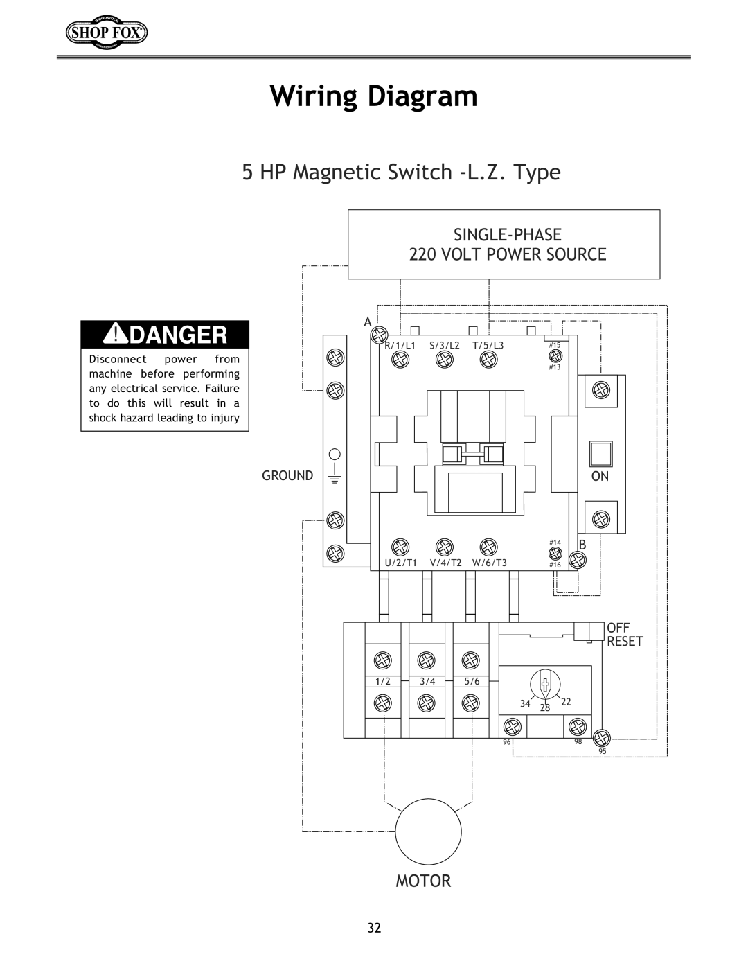
5 HP Magnetic Switch -L.Z. Type
SINGLE-PHASE 220 VOLT POWER SOURCE
RESET
TROUBLESHOOTING
CLOSURE
Page
X1683001
Page
6202Z
415 406 404 412 411 409 410 409 403 401 402
414 413 419 406 407 405 409 409 408 404 408
406 418 417
X1683201
ZZ4026
G8IKJ
JI@GK@FE
WARRANTY CARD
Name Street City StateZip Phone NumberE-MailFAX
MODEL # W1683 20 Planer
SERIAL#
WOODSTOCK INTERNATIONAL, INC P.O. BOX BELLINGHAM, WA
Place Stamp Here
FOLD ALONG DOTTED LINE