W1701 1HP Shaper
8. For custom fence facing, make sure the screw heads |
|
|
|
|
|
|
|
|
|
| |
| Safety |
| Safety |
| |
are countersunk completely below the surface of the |
|
|
| ||
| Guard |
| Guard Bar |
| |
fence face. |
|
|
| ||
|
|
|
|
| |
|
|
|
|
|
9.Connect the safety guard bar to the safety guard shaft with two
washers. See Figure 12.
10. Connect the safety guard to the safety guard bar |
|
|
|
|
|
|
|
|
|
|
|
| Fence |
|
|
|
|
|
|
| |
|
|
|
|
| Safety Guard |
|
| |||
with two |
|
| Housing |
|
|
|
|
| ||
|
|
|
|
| Shaft |
|
| |||
|
|
|
|
|
|
|
| |||
|
|
|
| |||||||
|
|
|
|
|
|
|
|
|
| |
11. Position the extension bar and safety guard on the |
|
| Figure 12. Guard and fence assembly. | |||||||
|
|
|
|
|
|
|
|
|
| |
main fence housing and install the |
|
|
|
|
|
|
|
|
|
|
See Figure 12. |
|
|
|
|
|
|
|
|
|
|
|
| Hold Spindle |
|
|
|
|
| |||
|
|
|
|
| ||||||
12. Position the guard as close as possible to the spin- |
|
| Here |
|
|
|
|
|
| |
|
|
|
|
|
|
|
|
|
| |
dle/cutter without impeding the feeding path of the |
|
|
|
|
|
|
|
|
|
|
workpiece. |
|
|
|
|
|
|
|
|
|
|
13. Place an 8mm |
|
|
|
|
|
|
|
|
|
|
(see Figure 13). |
|
|
|
|
|
|
|
|
|
|
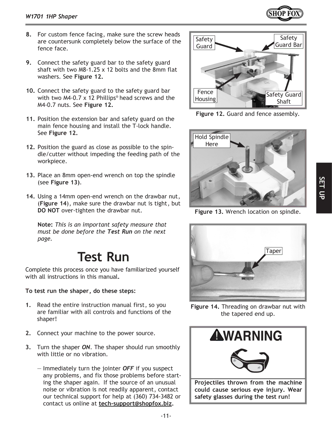
14. Using a 14mm |
|
|
|
|
|
|
|
|
|
|
(Figure 14), make sure the drawbar nut is tight, but |
|
|
|
|
|
|
|
|
|
|
DO NOT |
|
| Figure 13. Wrench location on spindle. | |||||||
Note: This is an important safety measure that |
|
|
|
|
|
|
|
|
|
|
|
|
|
|
|
|
|
|
|
| |
must be done before the Test Run on the next |
|
|
|
|
|
|
|
|
|
|
page. |
|
|
|
|
|
|
|
|
|
|
|
|
|
|
|
|
|
|
|
| |
Test Run |
|
|
|
|
|
| Taper |
|
| |
|
|
|
|
|
|
|
|
|
| |
Complete this process once you have familiarized yourself |
|
|
|
|
|
|
|
|
|
|
with all instructions in this manual. |
|
|
|
|
|
|
|
|
|
|
To test run the shaper, do these steps: |
|
|
|
|
|
|
|
|
|
|
1. Read the entire instruction manual first, so you |
|
|
|
|
|
|
| |||
Figure 14. Threading on drawbar nut with | ||||||||||
are familiar with all controls and functions of the |
|
|
|
| the tapered end up. | |||||
shaper! |
|
|
|
|
|
|
|
|
|
|
2. Connect your machine to the power source. |
|
|
|
|
|
|
|
|
|
|
|
|
|
|
|
|
|
|
|
| |
3. Turn the shaper ON. The shaper should run smoothly |
|
|
|
|
|
|
|
|
|
|
with little or no vibration. |
|
|
|
|
|
|
|
|
|
|
— Immediately turn the jointer OFF if you suspect |
|
|
|
|
|
|
|
|
|
|
any problems, and fix those problems before start- |
|
|
|
|
|
|
|
|
|
|
ing the shaper again. If the source of an unusual |
|
| Projectiles thrown from the machine |
| ||||||
noise or vibration is not readily apparent, contact |
|
| could cause serious eye injury. Wear | |||||||
our technical support for help at (360) |
|
| safety glasses during the test run! | |||||||
contact us online at |
|
|
|
|
|
|
|
|
|
|
|
|
|
|
|
|
|
|
|
| |
|
|
|
|
|
|
|
|
|
| |
SET UP