W1754 20" Planer With Mobile Base
6.Position the knife gauge over the knife as shown in
Figure 20.
7.Jack
8.Rotate the cutterhead to the first knife you started with. Slightly tighten all the gib bolts by following the tightening sequence shown in Figure 23. Repeat this step on the remaining knives.
9.Final tighten each gib bolt, then reinstall the top cover, dust hood and
OFF
Figure 22. Example of jack screw access
hole.
5 | 3 | 1 | 2 | 4 | 6 |
Figure 23. Gib bolt tigthening sequence.
SERVICE
Chain Tension
The chain drive can be adjusted to remove slack if the chain stretches over time or is loosened during table lev- eling procedures.
To adjust the chain tension, do these steps:
1.DISCONNECT THE PLANER FROM THE POWER SOURCE!
2.Remove the motor and front access panels.
NOTICE
During the next step, DO NOT let the chain fall off the sprockets. Returning the chain to its proper loca- tion without changing the table adjustments will be very difficult and time consuming.
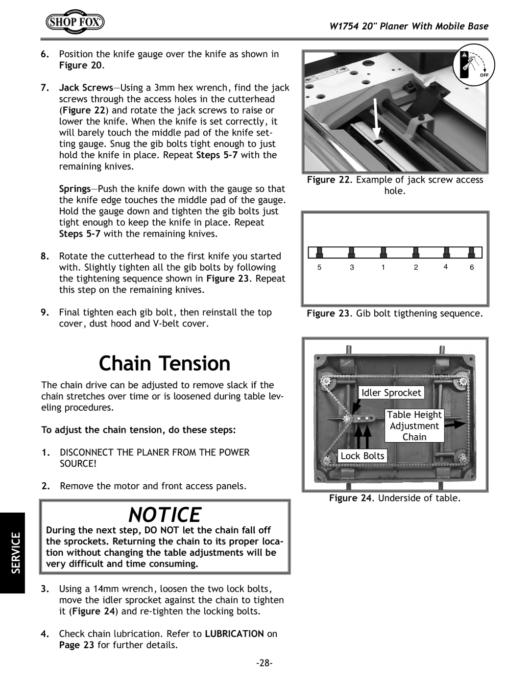
3.Using a 14mm wrench, loosen the two lock bolts, move the idler sprocket against the chain to tighten it (Figure 24) and
4.Check chain lubrication. Refer to LUBRICATION on Page 23 for further details.
Idler Sprocket
Table Height
Adjustment
Chain
Lock Bolts