W1754 20" Planer With Mobile Base
SET UP
Hardware and Tools (Not Shown) |
| |
• Hex Wrenches 3, 4, 5, 6mm | 4 | |
• Wrenches 8/10, 12/14, 17/19mm | 3 | |
• Set Screws | 6 | |
• Hex Bolts | 6 | |
• Flat Washers 8mm (Wings) | 6 | |
• Lock Washers 6mm (Wings) | 6 | |
• | Handwheel Bushing (Handwheel) | 1 |
• | Handwheel Handle (Handwheel) | 1 |
• Hex Nut | 1 | |
• Flat Washer 12mm (Handwheel) | 1 | |
• Key 4 x 4 x 20mm (Handwheel) | 1 | |
• Flange Bolts | 6 | |
Machine Placement
•Floor Load: This machine distributes a heavy load in a small footprint. Some floors may require additional bracing to support both machine and operator.
•Working Clearances: Consider existing and anticipated needs, size of material to be processed through the machine, and space for auxiliary stands, work tables or other machinery when establishing a location for your planer.
•Lighting: Lighting should be bright enough to eliminate shadow and prevent eye strain.
Lifting Planer
The cabinet stand on the Model W1754 is equipped with lifting bars to lift and place the planer.
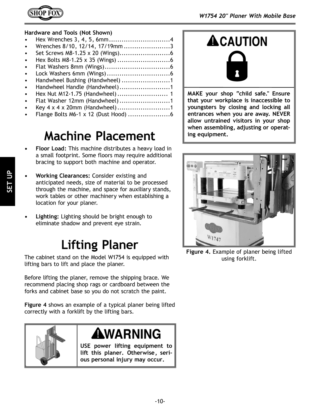
Before lifting the planer, remove the shipping brace. We recommend placing shop rags or cardboard between the forks and cabinet base so you do not scratch the paint.
Figure 4 shows an example of a typical planer being lifted correctly with a forklift by the lifting bars.
USE power lifting equipment to lift this planer. Otherwise, seri- ous personal injury may occur.
MAKE your shop “child safe." Ensure that your workplace is inaccessible to youngsters by closing and locking all entrances when you are away. NEVER allow untrained visitors in your shop when assembling, adjusting or operat- ing equipment.