W1754 20" Planer With Mobile Base
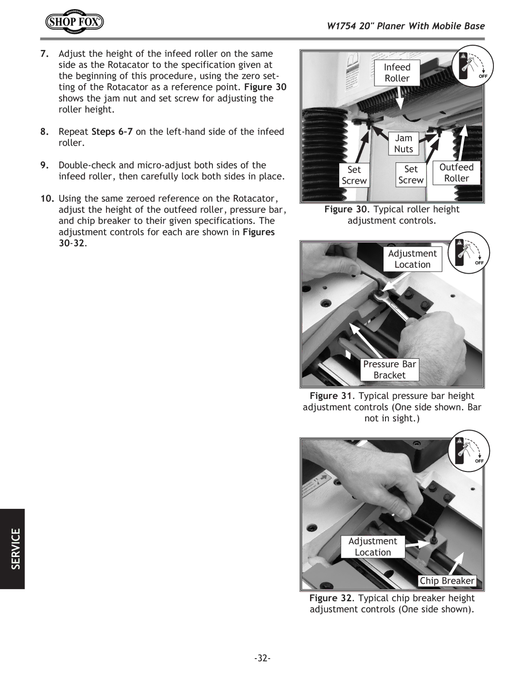
7.Adjust the height of the infeed roller on the same side as the Rotacator to the specification given at the beginning of this procedure, using the zero set- ting of the Rotacator as a reference point. Figure 30 shows the jam nut and set screw for adjusting the roller height.
8.Repeat Steps
9.
10.Using the same zeroed reference on the Rotacator, adjust the height of the outfeed roller, pressure bar, and chip breaker to their given specifications. The adjustment controls for each are shown in Figures
| Infeed |
|
| Roller | OFF |
|
| |
| Jam |
|
| Nuts |
|
Set | Set | Outfeed |
Screw | Screw | Roller |
Figure 30. Typical roller height | ||
adjustment controls. |
| |
Adjustment |
|
Location | OFF |
|
Pressure Bar
Bracket
Figure 31. Typical pressure bar height adjustment controls (One side shown. Bar not in sight.)
SERVICE
OFF |
Adjustment |
Location |
Chip Breaker |