W1770 21" Bandsaw w/Foot Brake
3.Familiarize yourself with the upper support bearing controls shown in Figures 27 & 28 on Page 23.
4.Loosen the guide block assembly cap screws and rotate the blade guide assembly
5.Tighten the guide block assembly cap screws.
6.Loosen the bolt on the support bearing adjustment
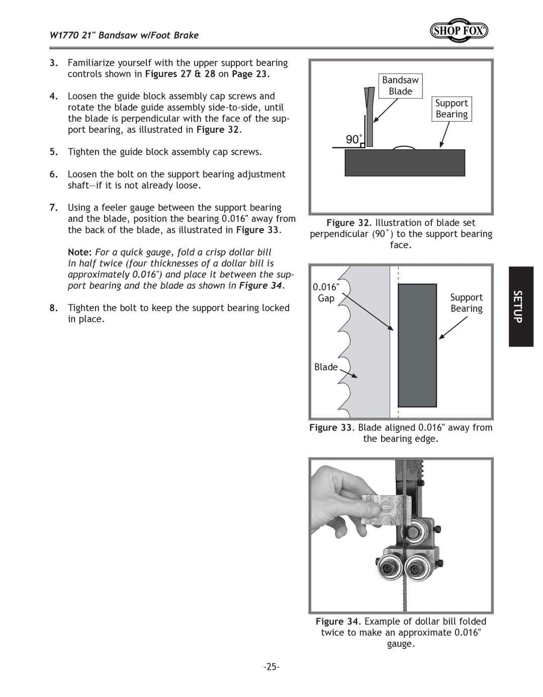
7.Using a feeler gauge between the support bearing and the blade, position the bearing 0.016" away from the back of the blade, as illustrated in Figure 33.
Note: For a quick gauge, fold a crisp dollar bill in half twice (four thicknesses of a dollar bill is approximately 0.016") and place it between the sup- port bearing and the blade as shown in Figure 34.
8.Tighten the bolt to keep the support bearing locked in place.
Bandsaw |
Blade |
Support |
Bearing |
Figure 32. Illustration of blade set
perpendicular (90˚) to the support bearing
face.
0.016" | Support |
Gap | |
| Bearing |
SETUP
Blade