Installation
Introduction
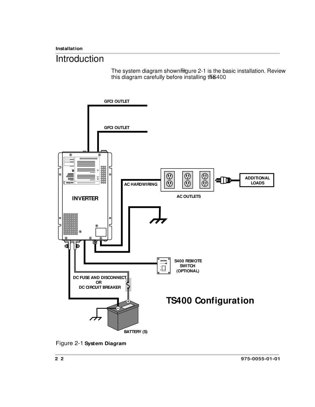
The system diagram shown in Figure
GFCI OUTLET
GFCI OUTLET
INVERTER
AC HARDWIRING
AC OUTLETS
ADDITIONAL
LOADS
DC FUSE AND DISCONNECT
OR
DC CIRCUIT BREAKER
Inverter ON | S400 REMOTE |
| SWITCH |
| (OPTIONAL) |
TS400 Configuration
BATTERY (S)