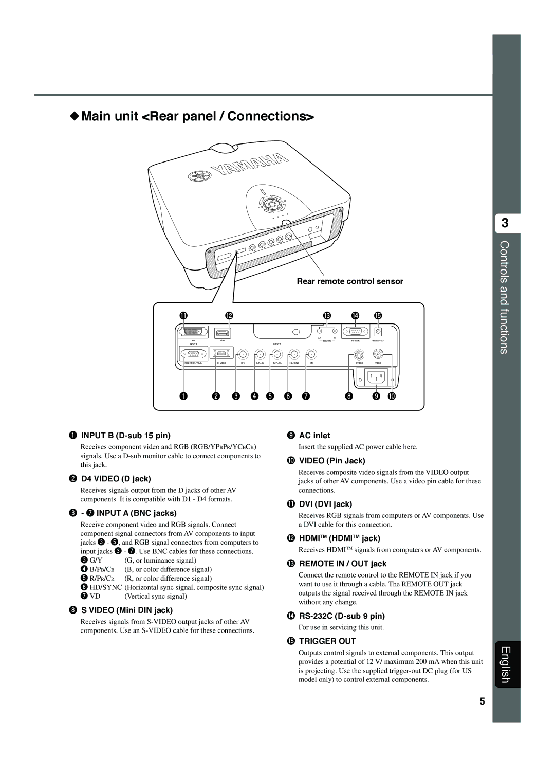
◆Main unit <Rear panel / Connections>
Rear remote control sensor
q | w |
|
|
| e | r | t | |
|
|
|
|
| OUT |
| IN |
|
DVI | HDMI |
|
|
|
| REMOTE | TRIGGER OUT | |
INPUT B |
|
| INPUT A |
|
|
|
|
|
RGB/YPBPR/YCBCR | D4 VIDEO | G/Y | B/PB/CBR/PR/CR | HD/SYNC | VD |
| S VIDEO | VIDEO |
1 | 2 | 3 | 4 5 | 6 | 7 |
| 8 | 9 0 |
3
Controls and functions
1INPUT B (D-sub 15 pin)
Receives component video and RGB (RGB/YPBPR/YCBCR) signals. Use a
2D4 VIDEO (D jack)
Receives signals output from the D jacks of other AV components. It is compatible with D1 - D4 formats.
3- 7 INPUT A (BNC jacks)
Receive component video and RGB signals. Connect
component signal connectors from AV components to input jacks 3 - 5, and RGB signal connectors from computers to input jacks 3 - 7. Use BNC cables for these connections.
3 G/Y | (G, or luminance signal) |
4B/PB/CB (B, or color difference signal)
5 R/PR/CR (R, or color difference signal)
6 HD/SYNC (Horizontal sync signal, composite sync signal)
7 VD | (Vertical sync signal) |
8S VIDEO (Mini DIN jack)
Receives signals from
9AC inlet
Insert the supplied AC power cable here.
0VIDEO (Pin Jack)
Receives composite video signals from the VIDEO output jacks of other AV components. Use a video pin cable for these connections.
qDVI (DVI jack)
Receives RGB signals from computers or AV components. Use a DVI cable for this connection.
wHDMITM (HDMITM jack)
Receives HDMITM signals from computers or AV components.
eREMOTE IN / OUT jack
Connect the remote control to the REMOTE IN jack if you want to use it through a cable. The REMOTE OUT jack outputs the signal received through the REMOTE IN jack without any change.
r
For use in servicing this unit.
tTRIGGER OUT
Outputs control signals to external components. This output provides a potential of 12 V/ maximum 200 mA when this unit is projecting. Use the supplied
English
5