Connections
Using the VIDEO AUX jacks on the front panel
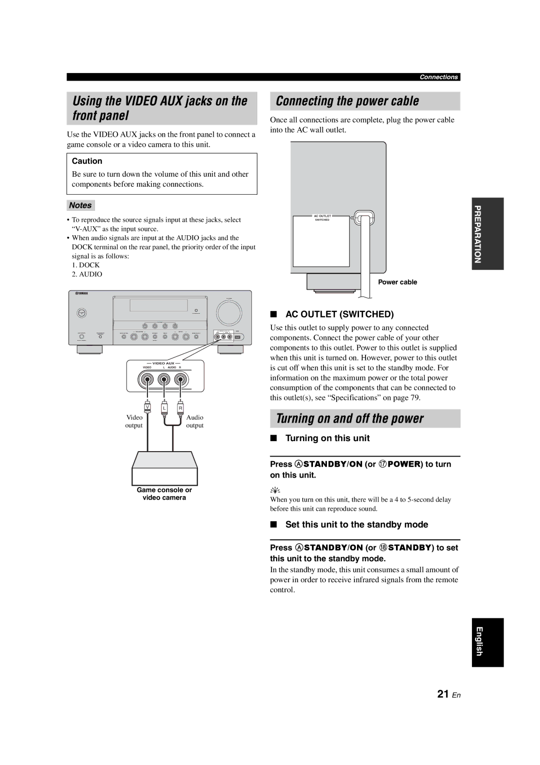
Use the VIDEO AUX jacks on the front panel to connect a game console or a video camera to this unit.
Caution
Be sure to turn down the volume of this unit and other components before making connections.
Connecting the power cable
Once all connections are complete, plug the power cable into the AC wall outlet.
Notes
•To reproduce the source signals input at these jacks, select
•When audio signals are input at the AUDIO jacks and the DOCK terminal on the rear panel, the priority order of the input signal is as follows:
1.DOCK
2.AUDIO
VOLUME
STANDBY/
ON | OPTIMIZER MIC |
SCENE
1 | 2 | 3 | 4 |
|
| l PROGRAM h |
| l | INPUT h |
| VIDEO AUX | USB |
PHONES | SPEAKERS | TONE CONTROL | STRAIGHT | DIRECT | AUDIO SELECT | VIDEO | L AUDIO | R |
| A/B/OFF |
|
|
|
|
|
|
|
SILENT CINEMA |
|
| EFFECT |
|
|
|
|
|
|
| VIDEO AUX |
|
|
VIDEO | L AUDIO R | |||
V | L | R |
Video |
| Audio |
output |
| output |
Game console or
video camera
ACACOUTLETS
SWITCHED
Power cable
■AC OUTLET (SWITCHED)
Use this outlet to supply power to any connected components. Connect the power cable of your other components to this outlet. Power to this outlet is supplied when this unit is turned on. However, power to this outlet is cut off when this unit is set to the standby mode. For information on the maximum power or the total power consumption of the components that can be connected to this outlet(s), see “Specifications” on page 79.
Turning on and off the power
■Turning on this unit
Press A STANDBY/ON (or GPOWER) to turn on this unit.
y
When you turn on this unit, there will be a 4 to
PREPARATION
■Set this unit to the standby mode
Press A STANDBY/ON (or HSTANDBY) to set
this unit to the standby mode.
In the standby mode, this unit consumes a small amount of power in order to receive infrared signals from the remote control.
English
