CLEARANCES
All units require particular clearances for proper operation and service. Refer to Table 6 for clearances required for con- struction, servicing, and proper unit operation.
Do not permit overhanging structures or shrubs to obstruct condenser air discharge outlet, combustion air inlet or vent outlets.
(1290)
Power Entry
(110)
| |||
| (435) |
| |
| (765) |
| |
|
| ||
59 | |||
(1500) | (615) | (155) | |
LEFT
Control
Entry Ø7/8 (22)
Power Entry
Convenience |
Power |
Outlet |
Entry |
Ø7/8 |
(22) |
ForDrain
Dimensions
SeeDetailB
27 ![]() 89
89
(685)(2260)
ForBaserail
FRONT Dimensions
SeeDetailA
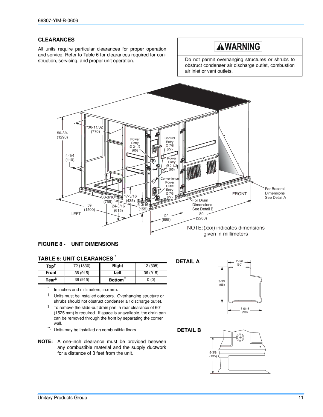
FIGURE 8 - UNIT DIMENSIONS
NOTE:(xxx)indicatesdimensions
giveninmilimeters
TABLE 6: UNIT CLEARANCES *
Top† | 72 (1830) | Right | 12 (305) |
Front | 36 (915) | Left | 36 (915) |
Rear‡ | 36 (915) | Bottom** | 0 (0) |
*.
†.Units must be installed outdoors. Overhanging structure or shrubs should not obstruct condenser air discharge outlet.
‡.To remove the
**. Units may be installed on combustible floors.
NOTE: A
DETAIL A | |
| |
| (60) |
(95)
(90)
DETAIL B
(135)
Unitary Products Group | 11 |