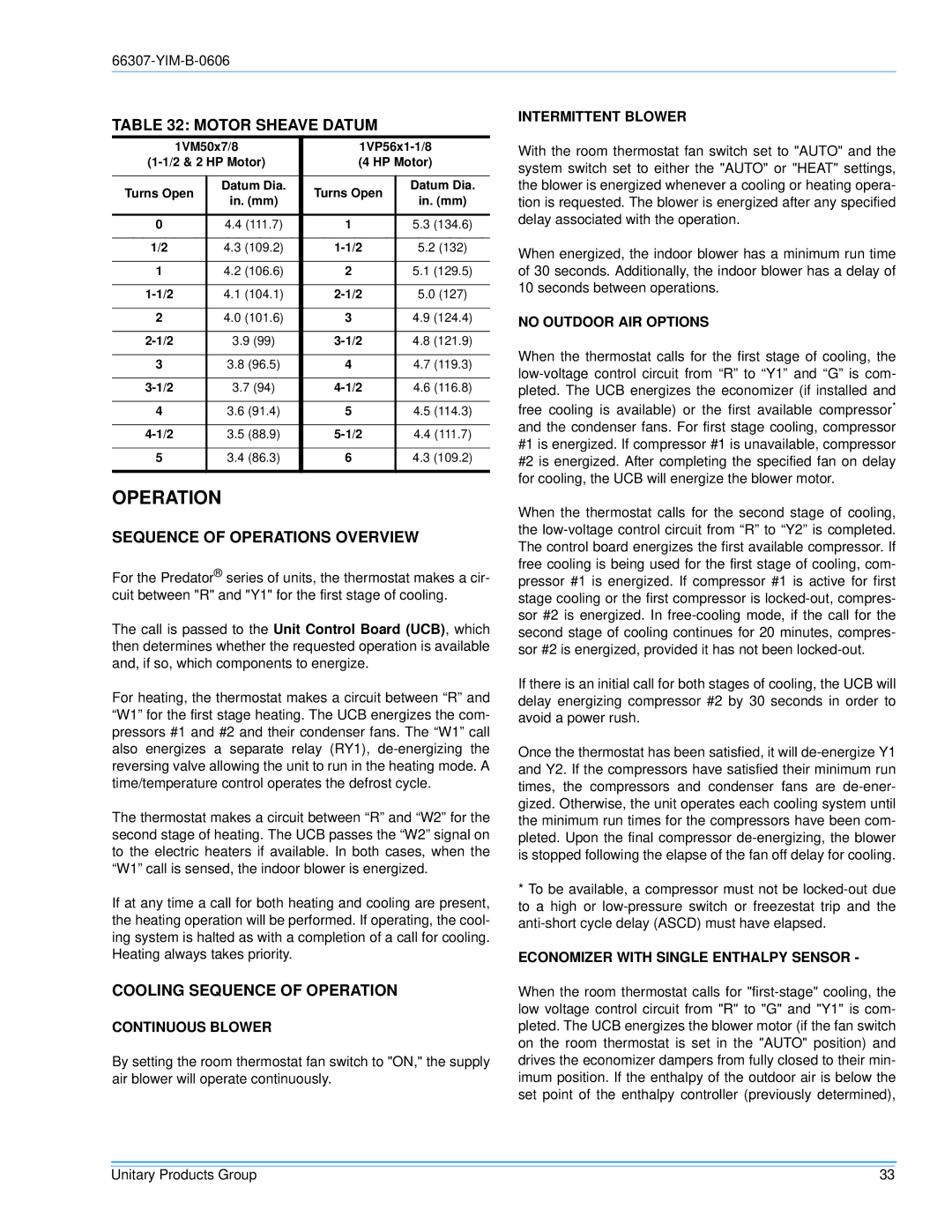
TABLE 32: MOTOR SHEAVE DATUM
| 1VM50x7/8 | ||||
(4 HP Motor) | |||||
|
|
|
|
| |
Turns Open | Datum Dia. | Turns Open | Datum Dia. | ||
in. (mm) | in. (mm) | ||||
|
|
| |||
|
|
|
|
| |
0 |
| 4.4 (111.7) | 1 | 5.3 (134.6) | |
|
|
|
|
| |
1/2 |
| 4.3 (109.2) | 5.2 (132) | ||
|
|
|
|
| |
1 |
| 4.2 (106.6) | 2 | 5.1 (129.5) | |
|
|
|
|
| |
| 4.1 (104.1) | 5.0 (127) | |||
|
|
|
|
| |
2 |
| 4.0 (101.6) | 3 | 4.9 (124.4) | |
|
|
|
|
| |
| 3.9 (99) | 4.8 (121.9) | |||
|
|
|
|
| |
3 |
| 3.8 (96.5) | 4 | 4.7 (119.3) | |
|
|
|
|
| |
| 3.7 (94) | 4.6 (116.8) | |||
|
|
|
|
| |
4 |
| 3.6 (91.4) | 5 | 4.5 (114.3) | |
|
|
|
|
| |
| 3.5 (88.9) | 4.4 (111.7) | |||
|
|
|
|
| |
5 |
| 3.4 (86.3) | 6 | 4.3 (109.2) | |
|
|
|
|
| |
OPERATION
SEQUENCE OF OPERATIONS OVERVIEW
For the Predator® series of units, the thermostat makes a cir- cuit between "R" and "Y1" for the first stage of cooling.
The call is passed to the Unit Control Board (UCB), which then determines whether the requested operation is available and, if so, which components to energize.
For heating, the thermostat makes a circuit between “R” and “W1” for the first stage heating. The UCB energizes the com- pressors #1 and #2 and their condenser fans. The “W1” call also energizes a separate relay (RY1),
The thermostat makes a circuit between “R” and “W2” for the second stage of heating. The UCB passes the “W2” signal on to the electric heaters if available. In both cases, when the “W1” call is sensed, the indoor blower is energized.
If at any time a call for both heating and cooling are present, the heating operation will be performed. If operating, the cool- ing system is halted as with a completion of a call for cooling. Heating always takes priority.
COOLING SEQUENCE OF OPERATION
CONTINUOUS BLOWER
By setting the room thermostat fan switch to "ON," the supply air blower will operate continuously.
INTERMITTENT BLOWER
With the room thermostat fan switch set to "AUTO" and the system switch set to either the "AUTO" or "HEAT" settings, the blower is energized whenever a cooling or heating opera- tion is requested. The blower is energized after any specified delay associated with the operation.
When energized, the indoor blower has a minimum run time of 30 seconds. Additionally, the indoor blower has a delay of 10 seconds between operations.
NO OUTDOOR AIR OPTIONS
When the thermostat calls for the first stage of cooling, the
free cooling is available) or the first available compressor* and the condenser fans. For first stage cooling, compressor #1 is energized. If compressor #1 is unavailable, compressor #2 is energized. After completing the specified fan on delay for cooling, the UCB will energize the blower motor.
When the thermostat calls for the second stage of cooling, the
If there is an initial call for both stages of cooling, the UCB will delay energizing compressor #2 by 30 seconds in order to avoid a power rush.
Once the thermostat has been satisfied, it will
*To be available, a compressor must not be
ECONOMIZER WITH SINGLE ENTHALPY SENSOR -
When the room thermostat calls for
Unitary Products Group | 33 |