| Simplicity™ Control | Disconnect location |
Terminal block for | board w/screw con- | (optional disconnect switch) |
nector for |
| |
| ||
ing and network |
| |
|
| |
| connection. |
|
Second model name- |
|
|
plate inside hinged |
|
|
access panel |
|
|
Compressor #2 access (high- efficiency com- pressor)
Base rails w/fork- ![]()
![]() lift slots (3 sides)
lift slots (3 sides)
and lifting holes)
Side entry | |
power and control | |
latch | wiring knockouts |
Filter access (2” | Filter drier (solid |
| |
| core) |
Condenser ![]() section
section
Slideout motor & blower assembly for easy access adjustment & service
![]()
Compressor #1 access (high- efficiency compressor)
connection
Roof curbs in eight- and
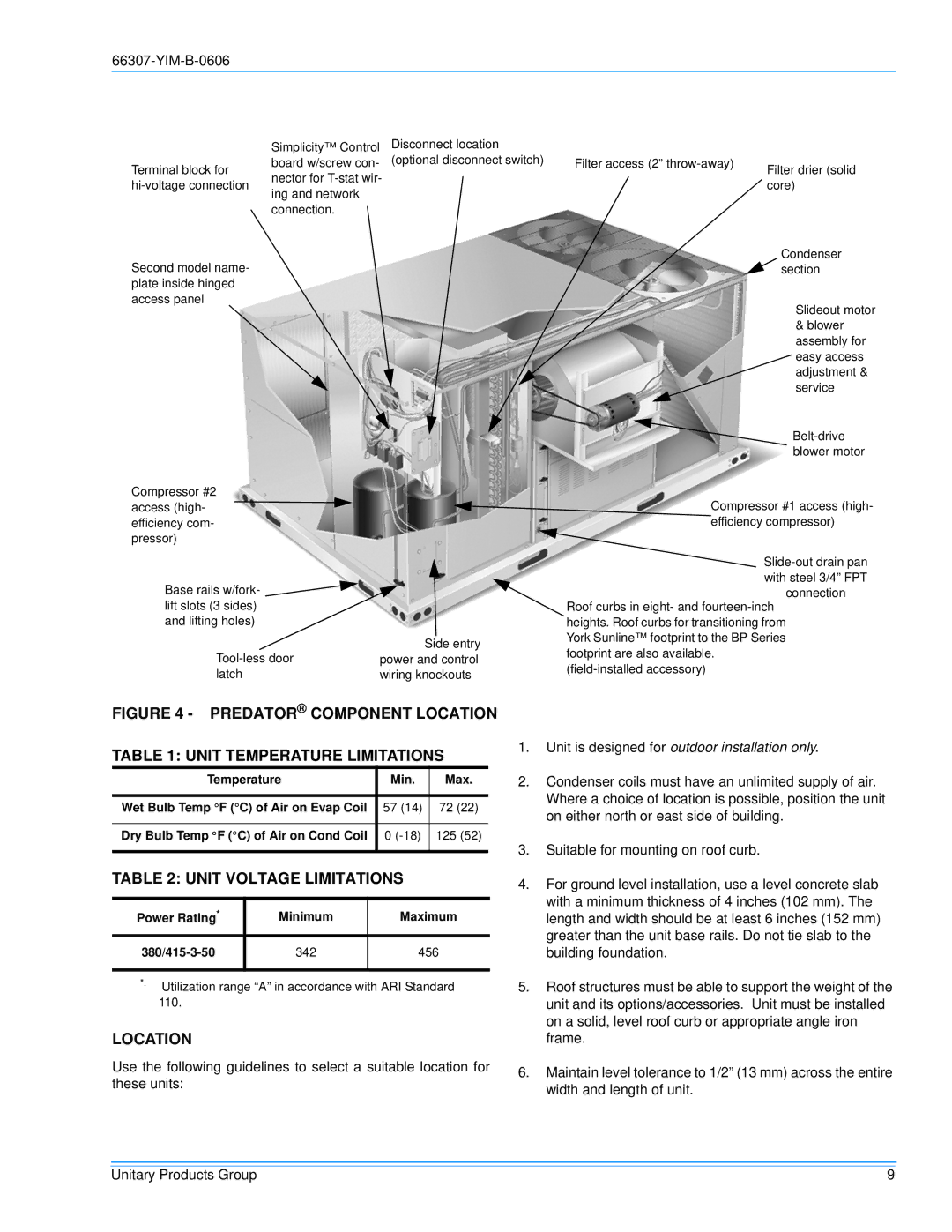
FIGURE 4 - PREDATOR® COMPONENT LOCATION
TABLE 1: UNIT TEMPERATURE LIMITATIONS
Temperature | Min. | Max. |
|
|
|
Wet Bulb Temp °F (°C) of Air on Evap Coil | 57 (14) | 72 (22) |
|
|
|
Dry Bulb Temp °F (°C) of Air on Cond Coil | 0 | 125 (52) |
|
|
|
TABLE 2: UNIT VOLTAGE LIMITATIONS
Power Rating* | Minimum | Maximum |
342 | 456 | |
|
|
|
*. Utilization range “A” in accordance with ARI Standard 110.
LOCATION
Use the following guidelines to select a suitable location for these units:
1.Unit is designed for outdoor installation only.
2.Condenser coils must have an unlimited supply of air. Where a choice of location is possible, position the unit on either north or east side of building.
3.Suitable for mounting on roof curb.
4.For ground level installation, use a level concrete slab with a minimum thickness of 4 inches (102 mm). The length and width should be at least 6 inches (152 mm) greater than the unit base rails. Do not tie slab to the building foundation.
5.Roof structures must be able to support the weight of the unit and its options/accessories. Unit must be installed on a solid, level roof curb or appropriate angle iron frame.
6.Maintain level tolerance to 1/2” (13 mm) across the entire width and length of unit.
Unitary Products Group | 9 |