Manuals
/
Yukon Advanced Optics
/
Household Appliance
/
Furnace
Yukon Advanced Optics
Oil Furnace Installation, Electric Wiring, Wiring The Furnace, Fig
Models:
Oil Furnace
1
23
64
64
Download
64 pages
37.66 Kb
20
21
22
23
24
25
26
27
Troubleshooting
Specifications
Install
Parts list
Wiring Diagrams
Electric Wiring
Maintenance
Draft Tube Assembly
TEST PROCEDURE Step
Accurately Adjust Flue Draft
Page 23
Image 23
Page 22
Page 24
Page 23
Image 23
Page 22
Page 24
Contents
LWO-112Oil Fired LWG-112Gas Fired
POLAR/EAGLE
Oil/Wood - Gas/Wood
Warm Air Central Heating Furnaces
or call 1-800-358-0060
FOR YOUR SAFETY
For repair or replacement parts
DANGER
MAINTENANCE
TABLE OF CONTENTS
PLAN YOUR INSTALLATION
INSTALLATION
extra safety precautions should be taken
Safety Statements
STOP FOR SAFETY
READ THROUGH THE ENTIRE MANUAL
FIG.
Unpack and Check Your Cartons
INSPECT SHIPMENT
PACKING LIST
xTHE OIL OR GAS BURNER FIRES INTO
Furnace Features - Eagle I - Husky
vMORE HEAT EXCHANGE SURFACE
MEANS LESS HEAT UP THE CHIMNEY
Furnace Features - Eagle I - Husky
yv x
~ w z u |
zFIRE BRICK LINING EXTENDS
Furnace Features - Eagle II - Polar
uYUKONTROL SOLID-STATE
Furnace Features - Eagle II - Polar
w|z u
1.0 G.P.H. - 80 H
Specifications
MODEL LWO-112Oil
Input rating
RULES FOR SAFE INSTALLATION AND OPERATION
Plan Your Installation
Unit Dimensions
PLAN YOUR INSTALLATION
Plan Your Installation
BE SURE TO INSTALL DUCT WORK
CLEARANCES TO COMBUSTIBLES
WITH CLEARANCES SHOWN
EVENT OF ELECTRIC POWER OR FURNACE FAN FAILURE
TYPICAL INSTALLATION
Plan Your Installation
BE INSTALLED WITH A METAL CONDENSATE PAN
SECONDARY AIR INTAKE COVER
Installation
DRAFT TUBE INSTALLATION
PLACE FURNACE
Install burner as follows
CUT AWAY VIEW BURNER COMBUSTION CHAMBER
Installation
OIL BURNER INSTALLATION
DAMPER CONTROL
Installation
Draft Tube Assembly
DRAFT
SMOKE BAFFLES
Installation
FIG. 14-A FIG. 14-B
Fan Limit Control
Installation
INSTALLING THE HONEYWELL FAN/LIMIT CONTROL
FIG.
Installation
TYPICAL THERMOSTAT SETTINGS
MOUNTING THE THERMOSTATS
SINGLE LINE SYSTEM
Installation
FIG.
FUEL TANKS AND FUEL LINES
FIG.
Installation
GAS PIPE SIZING
GAS PIPING
FIG.
Installation
Field Controls Model WMO-1Safety Switch
FUME SENSOR GAS MODELS ONLY
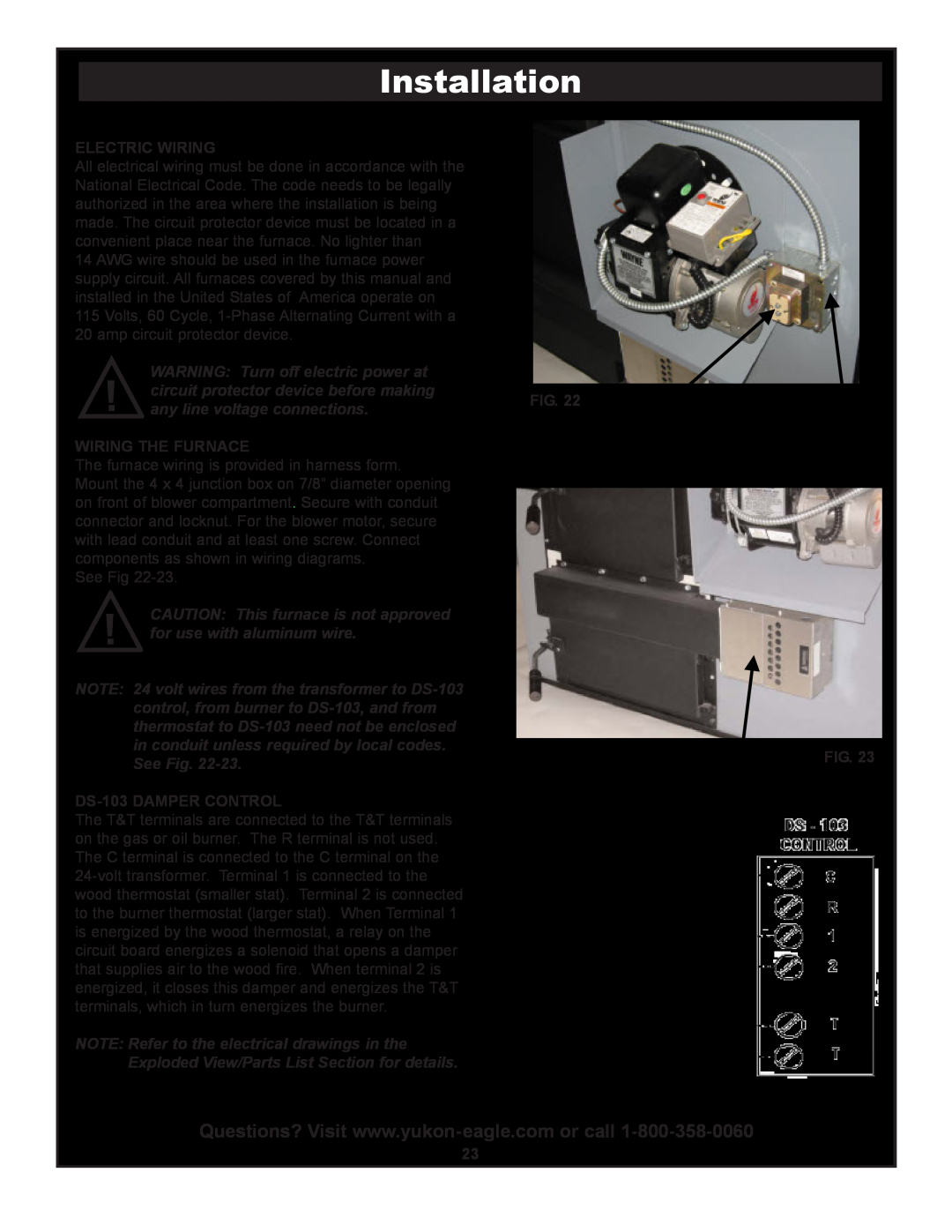
DS-103DAMPER CONTROL
Installation
ELECTRIC WIRING
WIRING THE FURNACE
OIL OR GAS AND WOOD HEATING WITH AIR CONDITIONING
24 Volt Field Wiring
OIL OR GAS AND WOOD HEATING ONLY
LESSER CLEARANCES TO COMBUSTIBLE
Installation
CONNECTING SMOKE PIPE
FIG.
MAKE THESE ADJUSTMENTS WHEN INSTALLING
ACCURATELY ADJUST FLUE DRAFT
A MANOMETER MUST BE USED TO
Installation
CHOOSING A CHIMNEY
Installation
PROPER CHIMNEYS
Installation
FIG. FIG
Installation
COMBUSTION AIR
FIG.
BTU Per Hour Input
Installation
STARTING BURNER AFTER IGNITION FAILURE
To start the oil burner on a new installation
Operating Instructions
OIL FIRING THE UNIT
FIG.
Gas Firing the Unit
To Start the Gas burner on new installation
Operating Instructions
Equivalent
Operating Instructions
BEST WOOD TO BURN
BTU’s
HAND FIRING WOOD
Operating Instructions
STARTING WOOD FIRE WITH GAS OR OIL BURNER
MAINTAINING A COAL FIRE
HOW TO START A COAL FIRE
Operating Instructions
WHAT SIZE COAL SHOULD I BURN?
ON 1/2-INCHOPENING GRATES Optional
Operating Instructions
OPERATING INSTRUCTIONS FOR BURNING COAL
OIL AND WOOD HEATING ONLY
Wiring Diagrams
Wiring Diagrams
OIL AND WOOD HEATING WITH A/C
Wiring Diagrams
GAS AND WOOD HEATING ONLY
Wiring Diagrams
GAS AND WOOD HEATING WITH A/C
ASH DISPOSAL
Maintenance
RECOVERING UNBURNED COAL
GRATE CARE -ASHREMOVAL
Secondary Heat Exchanger Eagle I - Husky
Maintenance
CLEANING FURNACE AND CHIMNEY FLUE PIPES
SMOKE PIPE, CHIMNEY AND SECONDARY HEAT EXCHANGER
FIG. FIG. FIG. FIG.
Maintenance
FURNACE BLOWER ADJUSTMENT
DUCT WORK AND BLOWER SPEED ADJUSTMENT
Maintenance
FIG.
Maintenance
TESTING INSTALLATIONS FOR EFFICIENCY
Step
Maintenance
TEST PROCEDURE Step
Step
Models LWO-112& LWG-112ONLY Fig. Lower Row
Maintenance
FIREBRICK PLACEMENT
FIREBRICK PLACEMENT
MAINTENANCE AT THE START OF THE HEATING SEASON
Maintenance
OIL BURNER MAINTENANCE
MAINTENANCE AT THE END OF THE HEATING SEASON
CREOSOTE-FORMATIONAND NEED FOR REMOVAL
Maintenance
HOW TO PREVENT RUST AND CORROSION
DISPOSAL OF ASHES
FIG.
Maintenance
SMOKE IN THE FURNACE ROOM
Chimney causes
GAS OR OIL PART OF FURNACE TOO LARGE FOR THE HOME
Maintenance
OVER HEATING WHEN BURNING SOLID FUEL AS
YOUR PRIMARY SOURCE OF HEAT
EAGLE I - HUSKY MODELS LWO-112& LWG-112
Exploded Views & Parts List
Description
Exploded Views & Parts List
Left Hand
Right Hand
Exploded Views & Parts List
EAGLE II - POLAR MODELS LWO-168& LWG-168
Left Hand
Left Hand Shown
Exploded Views & Parts List
Key No
GUN ASSEMBLY
WAYNE MODEL MSR OIL BURNER
Exploded Views & Parts List
Part Description
BURNER COMPONENTS WAYNE MODEL MSR
Exploded Views & Parts List
MSR GUN ASSEMBLY DETAIL
Exploded Views & Parts List
WAYNE MODEL P250AF-DIN GAS BURNER
Part Number
BURNER COMPONENTS WAYNE MODEL P250AF-DIN
Exploded Views & Parts List
Part Description
THIS CIRCULATING FAN PERFORMANCE CURVE
CIRCULATING FAN PERFORMANCE CURVE CHART
CHART IS FOR DETERMINING MOTOR HORSEPOWER NEEDS
MODELS LWO-112AND LWG-112
CHART IS FOR DETERMINING MOTOR HORSEPOWER NEEDS
MODELS LWO-168AND LWG-168
Exploded Views & Parts List
CIRCULATING FAN PERFORMANCE CURVE CHART
SERVICE HINTS- OIL
Troubleshooting
Notes
OWNERS MANUAL
HOW TO ORDER REPAIR PARTS
Assembly Installation Operation Repair Parts
YUKONEAGLE
Top
Page
Image
Contents