| Zhone Technologies, Inc. | IMACS Product Book, Version 4 | |
|
|
|
|
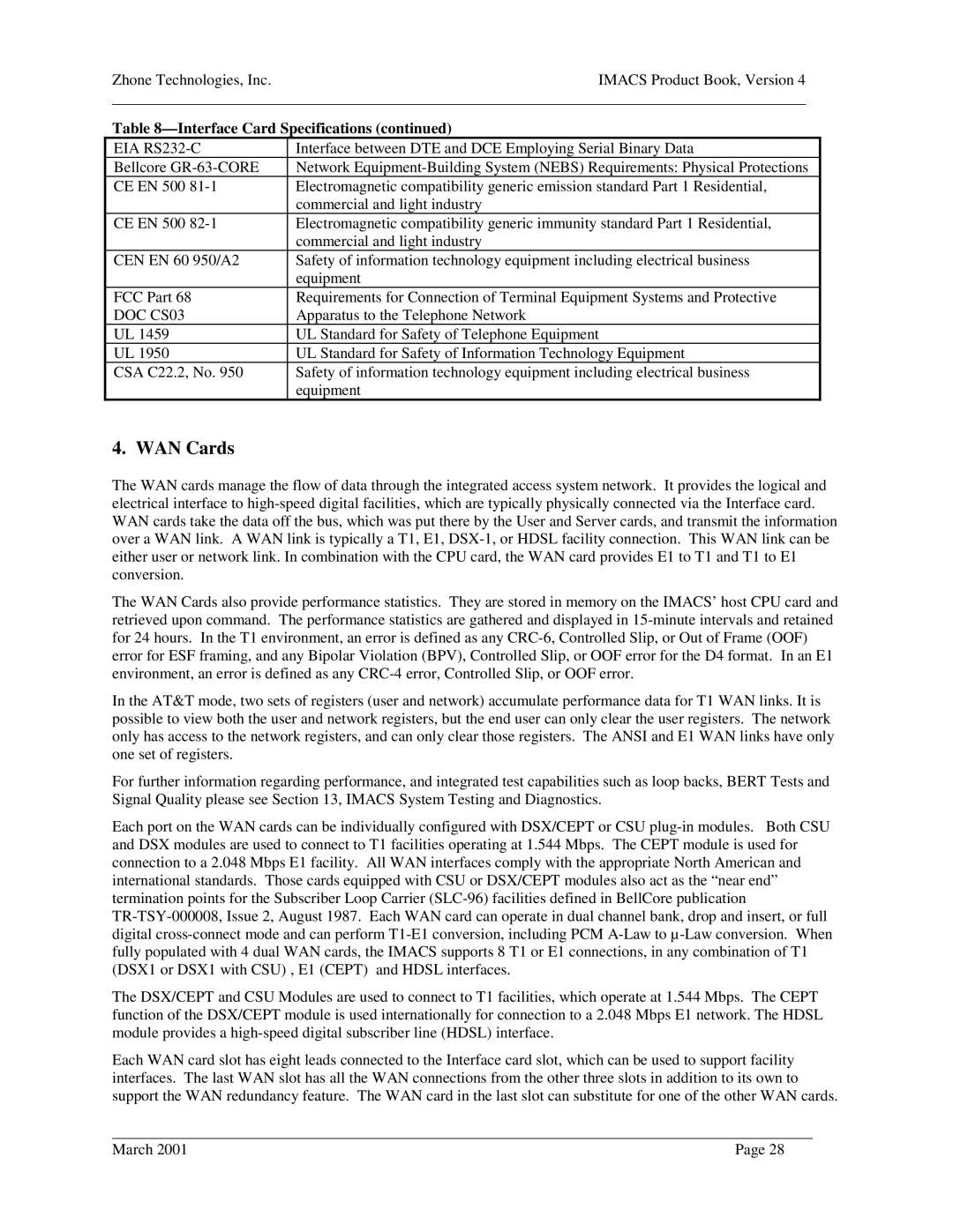
| Table | ||
| EIA | Interface between DTE and DCE Employing Serial Binary Data | |
| Bellcore | Network | |
| CE EN 500 | Electromagnetic compatibility generic emission standard Part 1 Residential, | |
|
| commercial and light industry | |
| CE EN 500 | Electromagnetic compatibility generic immunity standard Part 1 Residential, | |
|
| commercial and light industry | |
| CEN EN 60 950/A2 | Safety of information technology equipment including electrical business | |
|
| equipment | |
| FCC Part 68 | Requirements for Connection of Terminal Equipment Systems and Protective | |
| DOC CS03 | Apparatus to the Telephone Network | |
| UL 1459 | UL Standard for Safety of Telephone Equipment | |
| UL 1950 | UL Standard for Safety of Information Technology Equipment | |
| CSA C22.2, No. 950 | Safety of information technology equipment including electrical business | |
|
| equipment | |
4. WAN Cards
The WAN cards manage the flow of data through the integrated access system network. It provides the logical and electrical interface to
The WAN Cards also provide performance statistics. They are stored in memory on the IMACS’ host CPU card and retrieved upon command. The performance statistics are gathered and displayed in
In the AT&T mode, two sets of registers (user and network) accumulate performance data for T1 WAN links. It is possible to view both the user and network registers, but the end user can only clear the user registers. The network only has access to the network registers, and can only clear those registers. The ANSI and E1 WAN links have only one set of registers.
For further information regarding performance, and integrated test capabilities such as loop backs, BERT Tests and Signal Quality please see Section 13, IMACS System Testing and Diagnostics.
Each port on the WAN cards can be individually configured with DSX/CEPT or CSU
The DSX/CEPT and CSU Modules are used to connect to T1 facilities, which operate at 1.544 Mbps. The CEPT function of the DSX/CEPT module is used internationally for connection to a 2.048 Mbps E1 network. The HDSL module provides a
Each WAN card slot has eight leads connected to the Interface card slot, which can be used to support facility interfaces. The last WAN slot has all the WAN connections from the other three slots in addition to its own to support the WAN redundancy feature. The WAN card in the last slot can substitute for one of the other WAN cards.
March 2001 | Page 28 |