Zhone Technologies, Inc. | IMACS Product Book, Version 4 |
NETWORK
MANAGEMENT
SNMP AGENT
NODE
MANAGEMENT
MODEM
TELNET
DSX
CSU
HDSL
T1
WAN CONNECTIVITY
G.703 CEPT
HDSL
SERVER FUNCTIONS
E1
ISDN PRI
FRAME RELAY
VT100 ![]()
RITS
EXTERNAL ALARMS
|
| I/O X CONNECT |
| VOICE COMP |
| |
|
|
|
| |||
|
|
| MANAGEMENT | |||
|
|
|
|
| ||
|
|
|
|
| COMMUNICATION |
|
C |
|
|
|
| ||
|
|
| ATM |
| ||
|
|
|
| |||
|
|
|
|
|
| |
|
|
|
|
|
|
|
VOICE
FXO
FXS
E&M
|
|
|
|
|
|
|
|
|
|
|
|
|
|
DATA |
|
| LAN |
|
| DIGITAL |
|
| |||||
|
|
|
|
|
|
|
|
| ACCESS |
|
| ||
|
|
|
|
|
|
|
|
|
|
|
|
|
|
|
|
|
|
|
|
|
|
|
|
| |||
|
|
|
| IP/IPX ROUTING |
|
| |||||||
|
|
|
|
|
| ||||||||
|
| n x 56/64 |
|
|
|
|
|
|
| ||||
|
|
|
|
|
|
|
|
| |||||
|
| FRAD |
|
| BRIDGING |
|
| G.703 | |||||
|
|
|
|
|
| ||||||||
ISDN
BRI
‘U’ INTERFACE
‘S/T’ INTERFACE
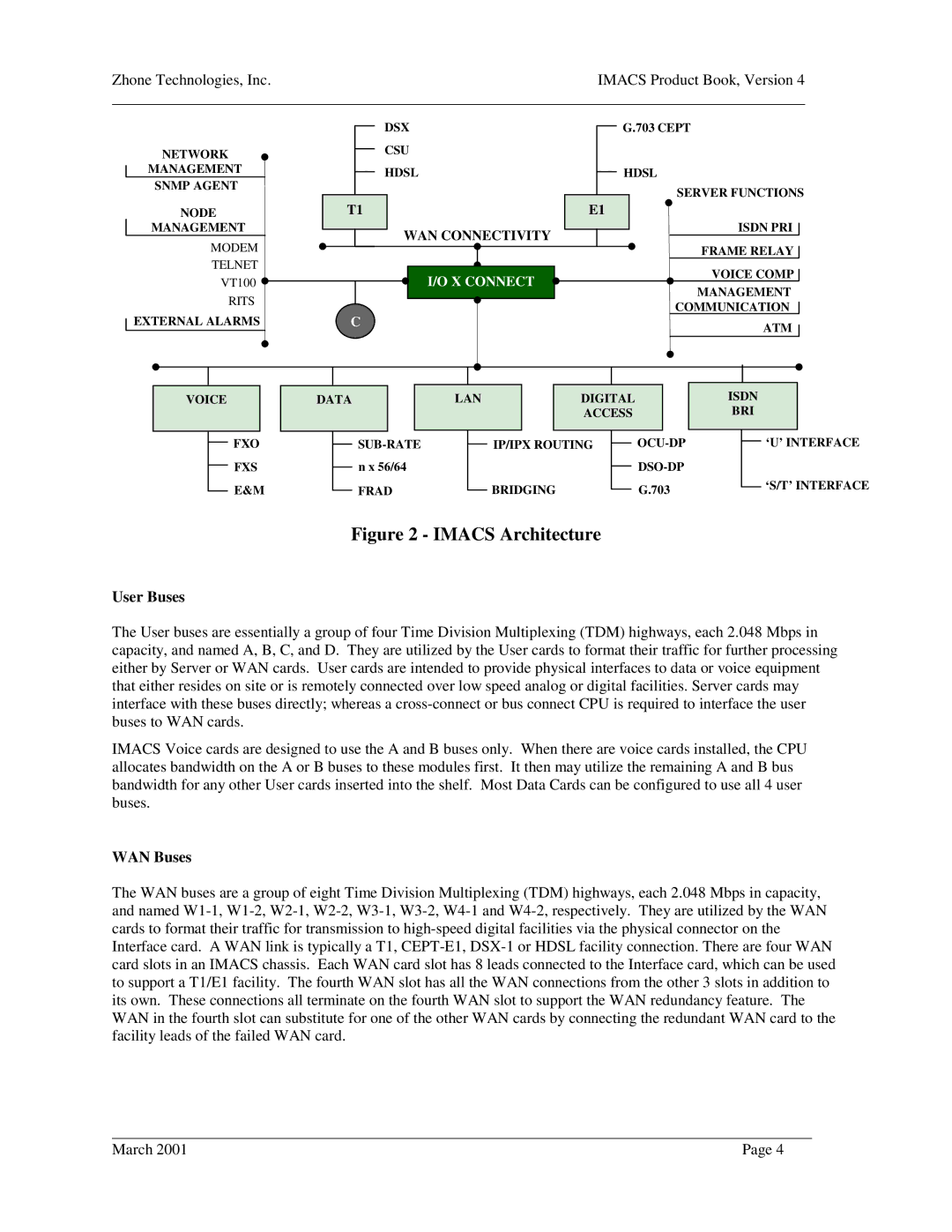
Figure 2 - IMACS Architecture
User Buses
The User buses are essentially a group of four Time Division Multiplexing (TDM) highways, each 2.048 Mbps in capacity, and named A, B, C, and D. They are utilized by the User cards to format their traffic for further processing either by Server or WAN cards. User cards are intended to provide physical interfaces to data or voice equipment that either resides on site or is remotely connected over low speed analog or digital facilities. Server cards may interface with these buses directly; whereas a
IMACS Voice cards are designed to use the A and B buses only. When there are voice cards installed, the CPU allocates bandwidth on the A or B buses to these modules first. It then may utilize the remaining A and B bus bandwidth for any other User cards inserted into the shelf. Most Data Cards can be configured to use all 4 user buses.
WAN Buses
The WAN buses are a group of eight Time Division Multiplexing (TDM) highways, each 2.048 Mbps in capacity, and named
March 2001 | Page 4 |