Agilent Part No Microfiche Part No Update April
Programming Guide
Safety Guidelines
Contents
Abor
Status Reporting
Synchronizing Power Module Output Changes
Error Messages
Introduction
About This Guide
Documentation Summary
External References
VXIplug&play Power Products Instrument Drivers
Downloading and Installing the Driver
Accessing Online Help
Supported Applications
Gpib Capabilities Of The Power Module
Introduction To Programming
Module Gpib Address
Introduction To Scpi
RST *IDN? *SRE
Volt LEV Prot Curr
Voltlev 8.0 Prot 8.8 CURR?
Outpprotdel
Traversing the Command Tree
Effect of Optional Headers
Outputprotectionclear STATUSOPERATIONCONDITION?
OUTPUTPROTECTIONCLEARSTATUSOPERATIONCONDITION?
Voltagelevel 7PROTECTION 8CURRENTLEVEL 3MODE List
Volttrig 7.5INIT*TRG Outp OFF*RCL 2OUTP on
Symbol
Numerical Data Formats Talking Formats
Listening Formats
Suffixes and Multipliers Class Unit Unit with Multiplier
System Considerations
Assign @PM3TO
Error Handling
Agilent Basic Controllers
Using the National Instruments Gpib Interface
Sending the Command Volt 5 in Basic
Sending the Command Volt 5 in C
Receiving Data from the Module
Receiving Module Data with Basic
Receiving Module Data with C
Language Dictionary
Introduction
Description Of Common Commands
CLS
Meaning and Type
Description
Bit Configuration of Standard Event Status Enable Register
ESE
ESE
ESR?
IDN?
OPC
OPC?
OPT?
PSC
RCL
RCL
RST
SAV
SRE
SRE
Bit Configuration of Status Byte Register
STB?
TRG
Description of Subsystem Commands
TST?
WAI
Abor
Subsystem Tree Diagram Calibration Subsystem
Calauto
Calauto 1 Calauto Once
Calcurr
Calcurrlev
Calpass
Calsave
Calstat
Calvolt
Calvoltlev
Calvoltprot
Curr
Curr 500 MA Currlev
Currmode
Currprotstat
Currprotstat OFF
Currtrig
Currtrig 1200 MA Currlevtrig
Init Initcont 1 Initcont on
Listcoun
Listcoun Listcoun INF
Listcurr
LISTCURRPOIN?
Listdwel
LISTDWELPOIN?
Liststep
Listvolt
Listvolt 2.0,2.5,3.0 Listvolt MAX,2.5,MIN
LISTVOLTPOIN?
MEASCURR? MEASVOLT?
Outp Outpstat ON,NORELAY
Outpprot
Outpprotcle Outpprotdel 75E-1
Outprel
Outprelpol
Norm
Outpttlt
Outpttlt 1 Outpttlt OFF
Outpttltlink
Outpttltsour Link
STATOPER?
STATOPEREVEN?
STATOPERCOND?
Statoperenab
Stat Oper NTR 32 Stat Oper PTR
Statpres
STATQUES?
STATQUESEVEN?
STATQUESCOND?
Stat Ques COND?
SYSTERR?
SYSTVERS?
Trigger Subsystem
Trig
Trig Trig IMM
Trigdel
Trigdel .25 Trigdel MAX
Triglink
Volt
Voltlev
Voltmode
Voltmode List Voltmode FIX
VOLTSENSSOUR?
Volttrig
Volttrig 1200 MV Voltlevtrig
Power Module Programming Parameters
Link Parameter List
Power Module Status Structure
Status Register Bit Configuration
Status Reporting
Operation Status Group
Bit Signal Bit Configurations of Status Registers Meaning
Status Questionable Commands Query
Questionable Status Group
Power Module Status Model
Standard Event Status Group
Status Byte Register
Output Queue
Location Of Event Handles
Initial Conditions At Power On
Examples
Statoperptr 5376ENAB
Statquesptr 18ENAB
STATOPEREVEN?QUESEVEN?
Statoperptr 1024NTR Statoperenab 1024*SRE
Synchronizing Power Module Output Changes
Trigger Subsystem
Model of Fixed-Mode Trigger Operation
Delaying State
Idle State
Initiated State
Model of List Mode Trigger Operation
INITiateCONTinuous Command
Trigger Status and Event Signals
Output Change State
Outpttltsour
List Subsystem
Listvolt 3.0,3.25,3.5,3.75 Listdwel 10,10,25,40
Automatically Repeating a List
Listcurr 2,3,12,15
Triggering a List
Timing diagrams of Liststep Operation
DFI Discrete Fault Indicator Subsystem
Scpi Command Completion
RI Remote Inhibit Subsystem
Error Messages
Power Module Hardware Error Messages
System Error Messages
Standard Event Status Register Error Bits
222 -223 -241 -310 -330 -350 -400 -410 -420 -430
Scpi Confirmed Commands
Scpi Approved Commands
Scpi Conformance Information
Scpi Version
Non-SCPI Commands
Application Programs
Application 1. Sequencing Multiple Modules During Power Up
Figure B1-1. Block Diagram of Application #1
Variations On This Implementation
Figure B1-2. Timing Diagram of Application #1
Reset and Clear Module
Enable Backplane TTL Trigger Drive
Enable Output
Enable Response to Trigger
Implementation Details How The MPS Implements The Solution
MPS Set Up
Figure B2-1. Block Diagram of Application #2
When a CV-TO-CC Transition Occurs
Enable TTL Trigger Drive
Enable Response to TTL Trigger
Start AT 15
Application 3. Controlling Output Voltage Ramp Up at Turn On
Figure B3-1. Simulating a Slow Voltage Ramp
Generating the Desired Voltage Ramp for Application #3
Option Base
Start Voltage for Ramp
Stop Voltage for Ramp
Seconds
Application 4. Providing Time-Varying Voltages
Figure B4-1. Voltage Waveform for Application #4
Module set up
Variations On This Implementation
Enable OCP
No Delay Before Protection Occurs
Enable Detection of OC Condition
Enables Detection on Positive TRANSITION, I.E
Application 5. Providing Time-Varying Current Limiting
Figure B5-1. Typical DUT Current vs. Time
Implementation Details How The MPS Implements The Sequence
GO to 12 V When Triggered
Current Limit Data
Dwell Time Data
SET to GET Current from List
Application 6. Output Sequencing Paced by the Computer
Nominal 12
MPS Set Up
Figure B6-1. Block Diagram of Application #6
These are the Bias
Supply Limit Conditions
To be Tested
Number of Bias Supply Limit C0MBINATIONS
Return
Overview Of Application
Advantages/Benefits Of The MPS Solution
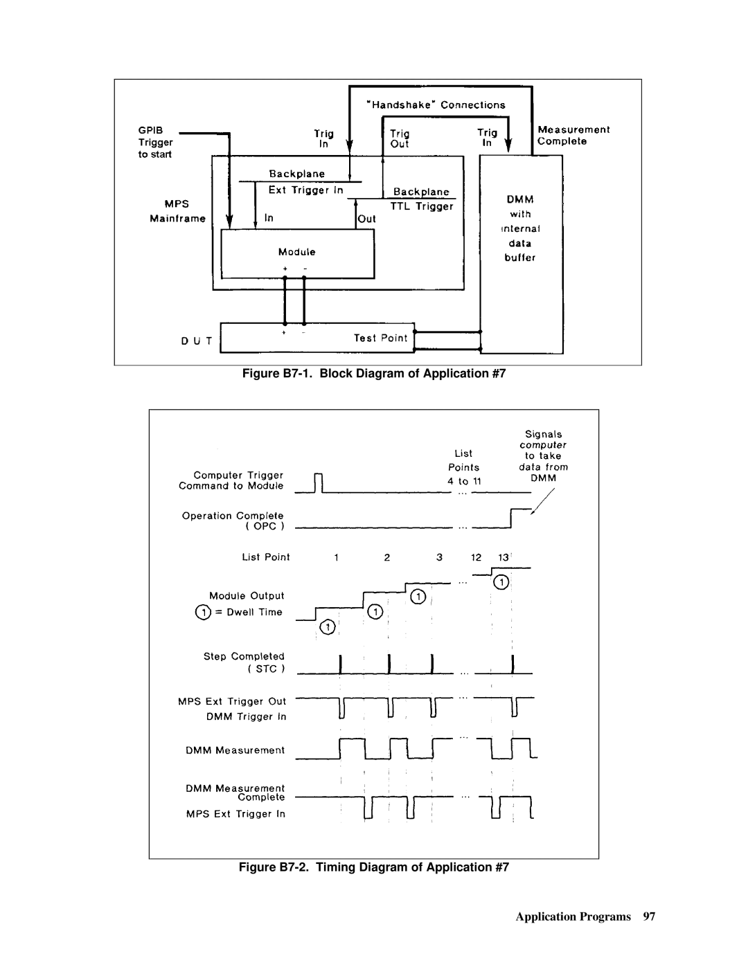
Figure B7-1. Block Diagram of Application #7
When the Module Indicates SIC Step Completed
When IT Completes the LIST. OPC Generates SRO
Enable SRQ Interrupt
Enable Intr Identify Handler Subroutine
Supplemental Information
CMD$ = Output on ‘ Enable Output
CMD$ = Initiate ‘ Enable Trigger to Start List
‘ Conversion to Send Real Numbers Over the BUS
CMD$ = Voltmode List ‘ SET to GET Voltage from List
Call Iooutputs SLOTO, CMDS, L
Waiting for Trigger BIT 5 of the Operation Status Register
CONDITION.DATA =
Wend
‘ Disable Auto Serial Poll
If IBSTA% 0 then Goto ‘ AS Part of the Command String
‘ Program N3.BAS
‘ INSTRUMENT.NAME$ = Sloto
‘ General Error Handler
If IBSTA% 0 then Goto Selected AS a Trigger Source
Stop
Application #3 Controlling Voltage Ramp UP AT Turn on
Dwell = ramptime
To terminate the iooutputa
Int error Char *badstring If error !=
EOl enabled for both read and write
Strcatvlist, vpoint
This is a generalized error checking routine
Index
Index
Index
Index
Index
Agilent Sales and Support Offices
United States Latin America
Manual Updates