Epson XDT manual Appendix, Sensor Mechanical

Page 47

40

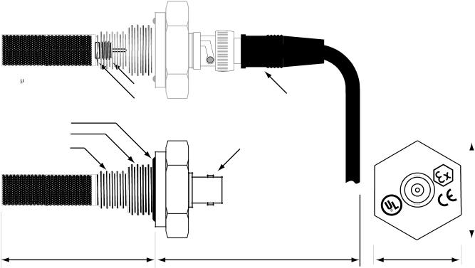
Removable Sensor encapsulated


in 100 sintered stainless steel,


unscrew to remove.

5/16"-24


tension washer

Viton A O-ring

3/4"-16

14mm x 1.25mm

2.230"

cable with molded-on male BNC connector

female BNC connector

3" min


U


A

R


T


N


C


00P


E


5


P

-


X

H


LISTED


76NM


flats for 11/4 " wrench


Appendix

XDT User’s Manual Appendices


C: Sensor Mechanical


~1.45"


Image 47
Contents Yyyyyyy y Sensor Serial No Instrument Serial No XDT User’s Manual Iii XDT User’s Manual Table of Contents Index Overview of the XDT XDT User’s Manual Sensor and Sampling Techniques Precautions using the sensor Sensor Installation & Sampling Techniques Sensor Technical SpecificationsNot Recommended In-situ InstallationExtractive Installation Mechanical Installation SAT Troubleshooting unexpected readingsElectromagnetic Compatibility Considerations Instrument Precautions using the XDTIsolation Instrument Technical SpecificationsXDT-NEMA IP65 Enclosure Installation InstallationInstrument Mechanical Installation XDT-PM DIN43700 Enclosure InstallationElectrical Connections Connecting PowerSensor Connection AC Mains Electrical Power ConnectionLow Voltage DC Powered Option Electrical Power Connection Wiring the Alarm ContactsInterfacing to the Analog Output Starting up Operating the InstrumentInterfacing to the RS-232 option Push Buttons Display Conventions12 3 4 5 6 7 8 Operating State Viewing Dewpoint ModeXDT User’s Manual Alarms Start Calibration HI **** ˚CSpanCheck Mode Single Point Self Calibration, manual or scheduled Instrument XDT User’s Manual SetUp State Viewing Serial Number ModeXDT User’s Manual Secured Password Protection Resetable Audio-Visual Alarm Option Nfpa compliant Troubleshooting the Instrument Display Explanation Required Action Maintenance XDT User’s Manual Glossary DB9 Glossary XDT User’s Manual Sign on message Calibration without key press Appendix a Flow Diagram of Operating State User InterfaceHere 16.24˚C˚F Appendix B Flow Diagram of Set-Up State User InterfaceSensor Mechanical AppendixAppendix D Optional Sensor Fittings Side View Appendix E XDT Circuit Board DimensionsAppendix E XDT-PM Enclosure Mounting Dimensions Appendix E XDT-NEMA Enclosure Mounting Dimensions Appendix F Sensor/SpanCheck Theory of Operation Appendix G Dewpoint Response time Analysis XDT User’s Manual Appendices Tested Instrument ˚C Appendix H Sample Gas Filter ConsiderationsSensor Appendix I XDT Grounding ConsiderationsAppendix J Analog Output vs. Dewpoint Instrument reading in ppmV Appendix K RS-232C Interface Protocol Help commandReceive Help Data Who Reset Login Data command K n m Error SensOpen or Error SensShort or Error SensSatLogin Command ? commandSerial Number Command Who CommandState User Interface Appendix L Procedure for Exchanging XDT SensorsAppendix M Uncertainty in LBS & ppmV calculations To obtain a RAN fill out this form and fax to 631 Xentaur Return Authorization Number Request FormPage Index Enclosure dimensions Pounds of H2O per million standard cubic Voltage, mains supply Iii Warranty