4. Control Panel
4-1. Control Panel
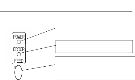
POWER LED lamp
Lights when the power switch is turned on and power is supplied to the printer.
ERROR LED lamp
Lights or blinks to indicate errors.
FEED switch
Pressing this switch once advances the paper one line. Holding down this switch advances paper continuously.
4-2. Error Indication
The ERROR LED lamp lights or blinks when the printer is in the following states.
Error status | ERROR LED |
No paper (paper end) | On |
Top cover open |
|
Printing stopped due to overheating of |
|
thermal head |
|
Power supply error |
|
Paper near end | Blinking |
The POWER LED lamp blinks when the printer is in the following states.
Error status | POWER LED |
Print head cable loose or disconnected | Blinking |
Temperature too low | |
Power supply error |
|
11